 English
 Espaol
 Franais
 阿拉伯
阿拉伯 中文(簡)
中文(簡) Deutsch
 Italiano
 Português
 日本
日本 韓國
韓國 български
 hrvatski
 esky
esky Dansk
Dansk Nederlands
 suomi
suomi Ελληνικ
 印度
印度 norsk
norsk Polski
 Roman
Roman русский
 Svenska
 珀金斯Perkins1103D-33(T)(TA)技術資料,珀金斯Perkins1103D-33(T)(TA)技術資料技術支持中心,珀金斯Perkins1103D-33(T)(TA)技術資料代理商,珀金斯Perkins1103D-33(T)(TA)技術資料銷售服務中心,珀金斯Perkins1103D-33(T)(TA)技術資料價格規格資料查詢,寧波日昕動力科技有限公司

珀金斯Perkins1103D-33(T)(TA)技術資料(英文)
詳細描述
Specifications
1103D Industrial Engine
XK (Engine)
XL (Engine)
XM (Engine)
This document has been printed from SPI². Not for Resale

![]()
![]()
![]()
![]()
Important Safety Information
Most accidents tha t involve produc t op eration, ma intena nc e and repair are caus ed by failure to
ob serve basic safety rules or precautions . An accident can often be avoided by recog nizing pote ntially
ha za rdous situations before an accident oc curs . A person mus t be alert to pote ntial ha za rds. This
person should also ha ve the ne cessary training, skills and tools to perform the se func tions properly.
Improper operation, lubrication, maintenance or repair of this product can be dangerous and
could result in injury or death.
Do not operate or perform any lubrication, maintenance or repair on this product, until you have
read and understood the operation, lubrication, maintenance and repair information.
Sa fety precautions and warning s are provided in this ma nua l and on the produc t. If the se ha za rd
warning s are not he eded, bod ily injury or death could oc cur to you or to othe r persons .
The ha za rds are identified by the “Safety Alert Symb ol” and followed by a “Signa l Word” suc h as
“DANGER”, “WARNING” or “CAUTION”. The Sa fety Alert “WARNING” label is shown below.
The me aning of this safety alert symb ol is as follows:
Attention! Become Alert! Your Safety is Involved.
The me ssage tha t appears und er the warning explains the ha za rd and can be either written or
pictorially presente d.
Op erations tha t ma y caus e produc t dama ge are identified by “NOTICE” labels on the produc t and in
this pub lication.
Perkins cannot anticipate every possible circumstance that might involve a potential hazard. The
warnings in this publication and on the product are, therefore, not all inclusive. If a tool, procedure,
work method or operating technique that is not specifically recommended by Perkins is used,
you must satisfy yourself that it is safe for you and for others. You should also ensure that the
product will not be damaged or be made unsafe by the operation, lubrication, maintenance or
repair procedures that you choose.
The informa tion, specifications , and illustrations in this pub lication are on the basis of informa tion tha t
was available at the time tha t the pub lication was written. The specifications , torque s, pressure s,
me asure me nts , adjustme nts , illustrations , and othe r items can cha ng e at any time. These cha ng es can
affect the service tha t is given to the produc t. Ob tain the comp lete and mos t current informa tion before
you start any job. Pe rkins dealers or Pe rkins distributors ha ve the mos t current informa tion available.
When replacement parts are required for this
product Perkins recommends using Perkins
replacement parts.
Failure to heed this warning can lead to prema-
ture failures, product damage, personal injury or
death.
This document has been printed from SPI². Not for Resale
![]()
![]()
KENR6911
3
Table of Contents
Table of Contents
Specifications Section
Engine Design .....................................................
Fuel Injection Lines ..............................................
Fuel Injection Pump .............................................
Fuel Injectors .......................................................
Fuel Transfer Pump .............................................
Lifter Group ...........................................................
Rocker Shaft ........................................................
Valve Mechanism Cover ......................................
Cylinder Head Valves ...........................................
4
4
5
6
6
7
7
8
8
Cylinder Head ...................................................... 11
Turbocharger ....................................................... 12
Exhaust Manifold ................................................. 13
Camshaft ............................................................. 13
Camshaft Bearings .............................................. 15
Engine Oil Filter ................................................... 15
Engine Oil Pump .................................................. 15
Engine Oil Pressure ............................................. 16
Engine Oil Bypass Valve ...................................... 17
Engine Oil Pan ..................................................... 17
Crankcase Breather ............................................. 18
Water Temperature Regulator and Housing ......... 19
Water Pump ......................................................... 20
Cylinder Block ...................................................... 20
Crankshaft ........................................................... 22
Crankshaft Seals ................................................. 24
Connecting Rod Bearing Journal ......................... 25
Main Bearing Journal ............................................ 25
Connecting Rod ................................................... 26
Piston and Rings .................................................. 27
Piston Cooling Jet ................................................. 28
Front Housing and Covers ................................... 29
Gear Group (Front) ............................................... 30
Flywheel ............................................................... 31
Flywheel Housing ................................................ 32
Crankshaft Pulley ................................................. 32
Fan Drive ............................................................. 32
Engine Lifting Bracket ........................................... 33
Alternator ............................................................. 33
Starter Motor ........................................................ 34
Glow Plugs ........................................................... 35
Index Section
Index ..................................................................... 36
This document has been printed from SPI². Not for Resale
![]()
4
KENR6911
Specifications Section
Specifications Section
When the camshaft is viewed from the front of
the engine, the camshaft rotates in the following
direction: ................................................... Clockwise
i02801123
The front of the engine is opposite the flywheel end.
The left side and the right side of the engine are
viewed from the flywheel end. The No. 1 cylinder is
the front cylinder.
Engine Design
Part No.: 290-8866
i02801124
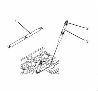
Fuel Injection Lines
Part No.: 290-8866
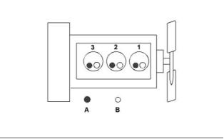
g01223241
Illustration 1
Cylinder and valve location
(A) Exhaust valve
(B) Inlet valve
Bore ......................................... 105 mm (4.133 inch)
Stroke ...................................... 127 mm (5.000 inch)
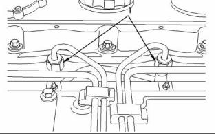
g01419468
Illustration 2
A typical fuel line
Displacement ...................................... 3.3 L (201 in )
3
(1) Tighten the union nuts for the fuel injector to the
following torque. ....................... 27 N·m (20 lb ft)
Cylinder arrangement ..................................... In-line
Type of combustion ............................ Direct injection
Compression ratio
Note: Tighten the union nuts at the fuel injection
pump to the following torque 27 N·m (20 lb ft).
Naturally aspirated engines ...................... 19.3:1
Turbocharged engines .............................. 18.2:1
Turbocharged engines .............................. 17.2:1
Number of cylinders ................................................ 3
Valves per cylinder .................................................. 2
Valve lash
Inlet valve ......................... 0.20 mm (0.008 inch)
Exhaust valve ................... 0.45 mm (0.018 inch)
Firing order ..................................................... 1, 2, 3
When the crankshaft is viewed from the front of
the engine, the crankshaft rotates in the following
direction: ................................................... Clockwise
This document has been printed from SPI². Not for Resale
![]()
![]()
![]()
KENR6911
5
Specifications Section
i02801125
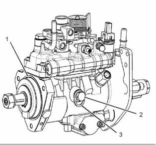
Fuel Injection Pump
Delphi DP210 and Delphi DP310
Note: Before the fuel injection pump is removed from
the engine the fuel injection pump shaft must be
locked. Position the engine to TC compression stroke
of number one cylinder before tightening the locking
screw. The locking screw will prevent the shaft from
rotating. If the fuel injection pump was removed
prior to correctly timing the engine and locking the
shaft, the fuel injection pump will need to be timed by
trained personnel.
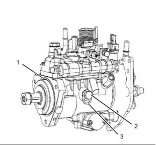
g01421823
Illustration 4
The Delphi DP 310 fuel injection pump
Note: The solenoid on the fuel injection pump is
a serviceable item. The fuel injection pump is a
nonserviceable item.
Note: A DP210 fuel injection pump is installed on the
naturally aspirated engine. A DP310 fuel injection
pump is installed on the turbocharged engine.
(1) O-ring
(2) Locking screw
(3) Washer
Locking the shaft
Loosen locking screw (2) and move the washer
(3) to the locked position. Tighten the bolt to the
following torque. .................... 14.5 N·m (11 lb ft)
Unlocking the shaft
Loosen locking screw (2) and install the washer
(3) to the unlocked position. Tighten the bolt to
the following torque. ................... 12 N·m (9 lb ft)
g01419475
Illustration 3
The Delphi DP 210 fuel injection pump
Note: The solenoid on the fuel injection pump is
a serviceable item. The fuel injection pump is a
nonserviceable item.
(1) O-ring
g00986531
(2) Locking screw
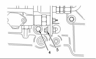
Illustration 5
Support bracket
(3) Washer
This document has been printed from SPI². Not for Resale
![]()
![]()
![]()
![]()
6
KENR6911
Specifications Section
(4) Tighten the mounting bolt to the following
torque. ...................................... 44 N·m (32 lb ft)
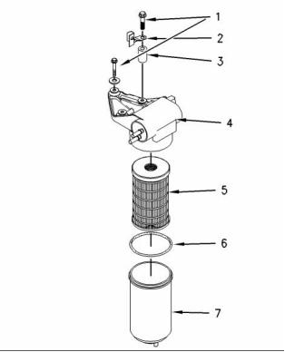
i02801146
Fuel Transfer Pump
(5) Tighten the mounting bolt and the nut to the
following torque. ....................... 22 N·m (16 lb ft)
Note: The support bracket must be installed after
the coolant pump is installed. In order to stop the
distortion of the timing case, finger tighten the bolt
(4) and then tighten the nut and bolt (5). Tighten the
bolt (4).
Tighten the bolts that hold the fuel pump to the front
housing to the following torque. ...... 25 N·m (18 lb ft)
i02801141
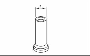
Fuel Injectors
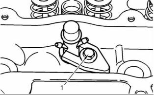
g00986823
Illustration 7
g00908211
Illustration 6
(1) Retaining bolts
(2) Clip
Fuel injector clamp
(1) Tighten the bolt in the clamp for the fuel injector
to the following torque. ............. 35 N·m (26 lb ft)
(3) Spacer
The fuel injector should be tested at the pressure in
Table 1.
(4) Fuel transfer pump
Type ................................... 12 volt electric motor
(5) Fuel filter element
Leakage in 10 seconds ................................. 0 drops
Table 1
(6) O ring
Service setting for the Fuel Injector
Injection Pressure
(7) Fuel filter bowl
29.4 + 0.8 MPa (4264 + 116 psi)
Note: Tighten the fuel filter bowl by hand. Rotate the
bowl 1/8 of a turn more by hand.
This document has been printed from SPI². Not for Resale
![]()
![]()

![]()
KENR6911
7
Specifications Section
i02801148
Lifter Group
SMC S Code: 1209
Part No.: 290-8866
S/N: XK11-Up
Part No.: 280-8866
S/N: XL11-Up
Part No.: 280-8866
S/N: XM11-Up
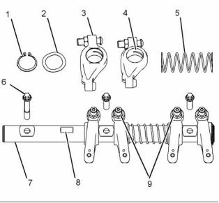
g01418665
Illustration 9
Note: In order to install the rocker shaft assembly,
Tooling (A) is required.
(1) Snap ring
g00629433
Illustration 8
(2) Washer
(1) Diameter of the lifter body .... 18.99 to 19.01 mm
(0.7475 to 0.7485 inch)
(3) Rocker arm
(4) Rocker arm bore
Clearance of the lifter in the cylinder block
bore ........... 0.04 to 0.09 mm (0.0015 to 0.0037 inch)
Diameter of the rocker arm bore for the
bushing ............................. 25.013 to 25.051 mm
(0.9848 to 0.9863 inch)
i02801152
Rocker Shaft
Rocker arm
Clearance between the rocker arm and the rocker
shaft ...................................... 0.026 to 0.089 mm
(0.0010 to 0.0035 inch)
Maximum permissible clearance between
the rocker arm bushing and the rocker
shaft .................................. 0.17 mm (0.007 inch)
(5) Spring
Note: Install the longest screw at the front of the
rocker shaft assembly.
Table 2
Required Tools
(6) Tighten the screws evenly. Begin in the center
and work toward the outside. Tighten the screws
to the following torque. ............. 35 N·m (26 lb ft)
Tool
Part Number
Part Description
Qty
A
27610227
Spacing Tool
1
(7) Rocker shaft
Diameter of the rocker
shaft .................................. 24.962 to 24.987 mm
(0.9828 to 0.9837 inch)
This document has been printed from SPI². Not for Resale
![]()
![]()

![]()
8
KENR6911
Specifications Section
(8) In order to install the rocker shaft assembly,
ensure that the machined square is to the top of
the rocker shaft.
i02830703
Cylinder Head Valves
(9) Locknut
Torque for the locknut ............... 27 N·m (20 lb ft)
Turbocharged Engines and
Turbocharged Aftercooled Engines
i02801157
Valve Mechanism Cover
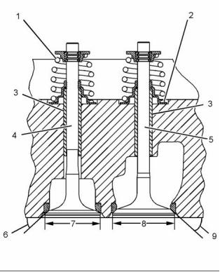
g01345407
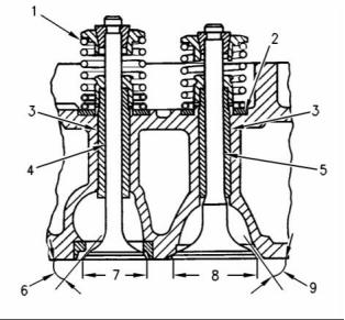
Illustration 11
A cross section of a cylinder head for a turbocharged engine and
turbocharged aftercooled engines
(1) Valve spring
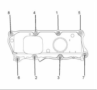
g01018519
Illustration 10
Typical example
The installed length of the valve
springs .......................... 36.17 mm (1.4240 inch)
The load for the installed valve spring ....... 312 N
(70 lb)
Tighten the bolts for the valve mechanism cover
in the sequence that is shown to the following
torque. ................................................. 9 N·m (7 lb ft)
(2) Valve spring recess
(3) The finished valve guides
Inside diameter of valve
guide ..................................... 9.000 to 9.022 mm
(0.3543 to 0.3552 inch)
Outside diameter of the valve
guide ................................. 13.034 to 13.047 mm
(0.5131 to 0.5137 inch)
This document has been printed from SPI². Not for Resale
![]()
![]()
![]()
KENR6911
9
Specifications Section
Interference fit of valve guide in cylinder
head ...................................... 0.007 to 0.047 mm
(0.0003 to 0.0019 inch)
(6) Exhaust valve face angle from the horizontal axis
Valve face angle ............................... 30 degrees
Valve seat angle ............................... 30 degrees
Length of Valve guide .......... 51.00 to 51.50 mm
(2.018 to 2.027 inch)
(7) Diameter of the exhaust
valve head ............................ 41.51 to 41.75 mm
Projection of the valve guide above the valve
spring recess (2) ................... 12.35 to 12.65 mm
(0.486 to 0.498 inch)
(1.634 to 1.643 inch)
(8) Diameter of the head of the inlet
valve ..................................... 46.20 to 46.45 mm
(1.8189 to 1.8287 inch)
Note: When new valve guides are installed, new
valves and new valve seat inserts must be installed.
The valve guides and the valve seat inserts are
supplied as partially finished parts. The unfinished
valve guides and unfinished valve seat inserts are
installed in the cylinder head. The guides and inserts
are then cut and reamed in one operation with special
tooling. This procedure ensures the concentricity of
the valve seat to the valve guide in order to create a
seal that is tight. Refer to Disassembly and Assembly
for removal and installation procedures.
(9) Angle of the inlet valve face from the vertical axis
Valve face angle ............................... 30 degrees
Valve seat angle ............................... 30 degrees
The valve lash is the following value when the engine
is cold:
Inlet valves ........................ 0.20 mm (0.008 inch)
Exhaust valves ................. 0.45 mm (0.018 inch)
(4) Exhaust valve
Diameter of the exhaust valve
stem ...................................... 8.938 to 8.960 mm
(0.3519 to 0.3528 inch)
Clearance of valve in valve
guide ..... 0.040 to 0.062 mm (0.0016 to 0.0024 inch)
Overall length of the exhaust
valve ................................... 128.184 to 128.634 mm
(5.0466 to 5.0643 inch)
The face of the exhaust valve is recessed below the
cylinder head by the following amount.
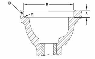
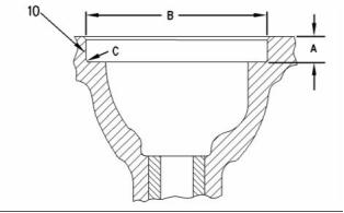
g00809016
Illustration 12
Turbocharged engines and turbocharged aftercooled
engines ..... 1.55 to 1.81 mm (0.0610 to 0.0713 inch)
Recess for the valve seat insert
(10) Machine the recess in the head for valve seat
inserts to the following dimensions.
Service limit ........................... 2.06 mm (0.0811 inch)
(5) Inlet valve
Recess for inlet valve seat for turbocharged
engines and turbocharged aftercooled engines
Diameter of the inlet valve
stem ...................................... 8.953 to 8.975 mm
(0.3525 to 0.3533 inch)
Clearance of valve in valve
guide .. 0.025 to 0.069 mm (0.001 to 0.0027 inch)
(A) .... 10.84 to 11.04 mm (0.4268 to 0.4346 inch)
(B) ..................................... 47.820 to 47.845 mm
(1.8827 to 1.8837 inch)
(C) Maximum radius ......... 0.38 mm (0.015 inch)
Recess for exhaust valve seat for turbocharged
engines and turbocharged aftercooled engines
Overall length of the inlet
valve ................................... 128.838 to 129.288 mm
(5.0724 to 5.0901 inch)
(A) .... 10.84 to 11.04 mm (0.4268 to 0.4346 inch)
(B) ..................................... 42.420 to 42.445 mm
(1.6701 to 1.6711 inch)
The face of the inlet valve is recessed below the
cylinder head by the following amount.
(C) Maximum radius ......... 0.38 mm (0.015 inch)
Turbocharged engines and turbocharged aftercooled
engines ..... 1.60 to 1.85 mm (0.0630 to 0.0728 inch)
Service limit .......................... 2.09 mm (0.0823 inch)
This document has been printed from SPI². Not for Resale
![]()
![]()
10
KENR6911
Specifications Section
Naturally Aspirated Engines
Note: When new valve guides are installed, new
valves and new valve seat inserts must be installed.
The valve guides and the valve seat inserts are
supplied as partially finished parts. The unfinished
valve guides and unfinished valve seat inserts are
installed in the cylinder head. The guides and inserts
are then cut and reamed in one operation with special
tooling. This procedure ensures the concentricity
of the valve seat to the valve guide in order to
create a seal that is tight. Refer to the Disassembly
and Assembly Manual for removal and installation
procedures.
(4) Exhaust valve
Diameter of the exhaust valve
stem ...................................... 8.938 to 8.960 mm
(0.3519 to 0.3528 inch)
Clearance of valve in valve
guide ....... 0.040 to 0.840 mm (0.0016 to 0.033 inch)
Overall length of the exhaust
valve ..... 128.92 to 129.37 mm (5.075 to 5.093 inch)
g00294082
Illustration 13
Cross section of naturally aspirated cylinder head
The face of the exhaust valve is recessed below the
cylinder head by the following amount.
(1) Valve spring
The installed length of the valve
springs .............................. 33.5 mm (1.318 inch)
Naturally aspirated engines ............ 0.53 to 0.81 mm
(0.021 to 0.032 inch)
The load for the installed valve springs ..... 254 N
(57.1 lb)
Service limit ............................ 1.06 mm (0.042 inch)
(5) Inlet valve
(2) Valve spring recess
Diameter of the inlet valve
stem ...................................... 8.953 to 8.975 mm
(3) The finished valve guides
(0.3525 to 0.3533 inch)
Clearance of valve in valve
guide .. 0.025 to 0.069 mm (0.001 to 0.0027 inch)
Inside diameter of valve
guide ..................................... 9.000 to 9.022 mm
(0.3543 to 0.3552 inch)
Overall length of the inlet
valve ..... 128.92 to 129.37 mm (5.075 to 5.093 inch)
Outside diameter of the exhaust valve
guide ................................. 13.034 to 13.047 mm
(0.5131 to 0.5137 inch)
The face of the inlet valve is recessed below the
cylinder head by the following amount.
Outside diameter of the inlet valve
guide ................................. 13.034 to 13.047 mm
(0.5131 to 0.5137 inch)
Interference fit of valve guide in cylinder
head ...................................... 0.007 to 0.047 mm
(0.0003 to 0.0019 inch)
Naturally aspirated engines ............ 0.58 to 0.84 mm
(0.023 to 0.033 inch)
Service limit ............................ 1.09 mm (0.043 inch)
(6) Exhaust valve face angle from the vertical axis
Length of Valve guide .......... 51.00 to 51.50 mm
(2.018 to 2.027 inch)
Valve face angle ............................... 30 degrees
Valve seat angle ............................... 30 degrees
Projection of the valve guide above the valve
spring recess (2) ................... 12.35 to 12.65 mm
(0.486 to 0.498 inch)
(7) Diameter of the exhaust
valve head ............................ 41.51 to 41.75 mm
(1.634 to 1.643 inch)
This document has been printed from SPI². Not for Resale
![]()
![]()
KENR6911
11
Specifications Section
(8) Diameter of the head of the inlet
i02801177
valve ... 46.20 to 46.45 mm (1.818 to 1.828 inch)
Cylinder Head
(9) Angle of the inlet valve face from the vertical axis
Valve face angle ............................... 30 degrees
Valve seat angle ............................... 30 degrees
The valve lash is the following value when the engine
is cold:
Inlet valves ........................ 0.20 mm (0.008 inch)
Exhaust valves ................. 0.45 mm (0.018 inch)
The cylinder head bolts are two different lengths. The
following information provides the proper torque for
the cylinder head bolts.
g00809016
Illustration 14
Recess for the valve seat insert
(10) Machine the recess in the head for valve seat
inserts to the following dimensions.
Recess for inlet valve seat for naturally aspirated
engines
(A) ..... 9.84 to 10.04 mm (0.3874 to 0.3952 inch)
(B) ..................................... 47.820 to 47.845 mm
(1.8826 to 1.8836 inch)
g01017007
(C) Maximum radius ......... 0.38 mm (0.015 inch)
Illustration 15
The tightening sequence
Recess for exhaust valve seat for naturally
aspirated engines
Lubricate the threads and the underside of the head
bolts with clean engine oil.
(A) ..... 9.84 to 10.04 mm (0.3874 to 0.3952 inch)
(B) ..................................... 42.420 to 42.445 mm
(1.6701 to 1.6711 inch)
Tighten the bolts in the sequence that is shown in
illustration 15 to the following torque. ...... 50 N·m
(37 lb ft)
(C) Maximum radius ......... 0.38 mm (0.015 inch)
Tighten the bolts again to the following
torque. .................................... 100 N·m (74 lb ft)
This document has been printed from SPI². Not for Resale
![]()
![]()
![]()
12
KENR6911
Specifications Section
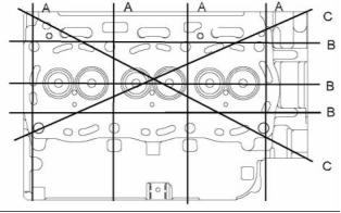
Table 3
Maximum Permissible
Distortion
Dimension
Width (A)
Height (B)
0.03 mm (0.0012 inch)
0.05 mm (0.0019 inch)
0.05 mm (0.0019 inch)
Diagonal Line (C)
i02801182
Turbocharger
g00905621
Illustration 16
Head bolts
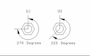
The head bolts require an additional torque turn
procedure. The numbers (1, 3, 4) are three long
cylinder head bolts. All the other bolts are short bolts.
The tightening sequence is shown in illustration 15.
Place an index mark on the top of each bolt
head. Tighten the short bolts for the additional
amount. ........................................... 225 degrees
Place an index mark on the top of each bolt
head. Tighten the long bolts for the additional
amount. ........................................... 270 degrees
Thickness of the cylinder head .. 117.95 to 118.05 mm
(4.643 to 4.647 inch)
Minimum thickness of cylinder head ........ 117.20 mm
(4.614 inch)
The maximum distortion of the cylinder head is given
in table 3.
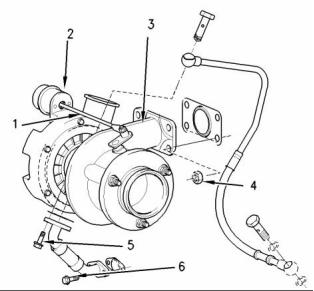
g00991357
Illustration 18
Typical turbocharger
(1) Actuator rod
(2) Actuator
(3) Turbocharger
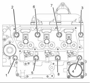
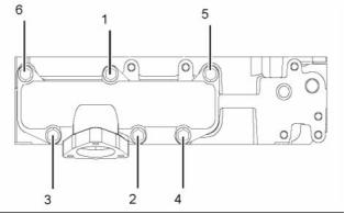
g01017008
Illustration 17
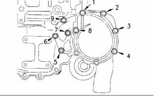
Cylinder head
Tighten the nuts(4) to the following torque. .... 44 N·m
(32 lb ft)
Tighten the bolt (5) to the following torque. ...... 9 N·m
(80 lb in)
This document has been printed from SPI². Not for Resale
![]()
![]()
![]()

![]()
KENR6911
13
Specifications Section
Tighten the bolt (6) to the following torque. .... 22 N·m
(16 lb ft)
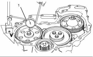
i02831537
Camshaft
The maximum test pressure for the
wastegate ....................................... 205 kPa (30 psi)
The movement for the rod actuator ................. 1 mm
(0.0394 inch)
Table 4
The part number for
the turbocharger
The pressure for the
wastegate
2674A715
2674A721
2674A722
101.5 ± 3 kPa
(14.7216 ± 0.4351 psi)
127 ± 3 kPa
(18.4201 ± 0.4351 psi)
154 ± 3 kPa
(22.3362 ± 0.4351 psi)
g01277351
Illustration 20
i02801183
Exhaust Manifold
Checking the end play of the camshaft
(1) End play of a new camshaft ..... 0.10 to 0.55 mm
(0.004 to 0.022 inch)
Maximum permissible end play of a worn
camshaft ................................. 0.60 mm (0.023 inch)
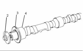
g01277354
Illustration 21
Typical camshaft
(2) Bolt
g01017009
Tighten the bolt to the following torque. ... 95 N·m
(70 lb ft)
Illustration 19
Note: The exhaust manifold must be aligned to the
cylinder head. Refer to Disassembly and Assembly
Manual for the correct procedure.
(3) Camshaft thrust washer
Thickness of the thrust
washer .................................. 5.486 to 5.537 mm
(0.2160 to 0.2180 inch)
Tighten the exhaust manifold bolts in the sequence
that is shown illustration 19 to the following
torque. ............................................. 33 N·m (24 lb ft)
Depth of the recess in the cylinder block for the
thrust washer ........................ 5.560 to 5.640 mm
(0.2189 to 0.2220 inch)
This document has been printed from SPI². Not for Resale
![]()

![]()
![]()
![]()
14
KENR6911
Specifications Section
Tolerance of the thrust washer in cylinder block
front face ........................... −0.154 to −0.023 mm
(−0.0061 to −0.0009 inch)
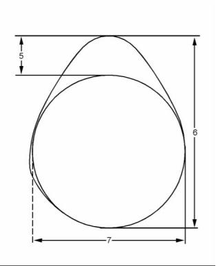
Turbocharged engines and turbocharged
aftercooled engines
Inlet lobe ............................... 7.266 to 7.366 mm
(0.2861 to 0.2900 inch)
Exhaust lobe ......................... 8.081 to 8.181 mm
(4) The diameters of the camshaft journals are given
in the following table.
(0.3181 to 0.3221 inch)
Table 5
(6) Camshaft lobe height
(7) Base circle
Diameters of Camshaft Journals
Camshaft Journals
Standard Diameter
50.711 to 50.737 mm
(1.9965 to 1.9975 inch)
To determine the lobe lift, use the procedure that
follows:
1
50.457 to 50.483 mm
(1.9865 to 1.9875 inch)
2 and 3
4
1. Mount the camshaft between centers.
49.949 to 49.975 mm
(1.9665 to 1.9675 inch)
2. By using a dial indicator in contact with the surface
of the lobe, rotate the camshaft and record the
maximum and minimum lift.
Maximum wear on the camshaft journals ... 0.05 mm
(0.0021 inch)
Note: There may be two lobes on the camshaft.
Refer to illustration 22. The surface between the
lobes may not return to the radius of the base circle.
Using a micrometer to measure the diameter of the
base circle may give a inaccurate result.
3. Subtract the smallest dimension from the largest
dimension. The difference is the actual camshaft
lobe lift.
Maximum permissible deviation between the
actual lobe lift and the specified lobe lift of a new
camshaft ................................. 0.05 mm (0.002 inch)
g01345411
Illustration 22
Typical example
(5) Camshaft lobe lift
Naturally aspirated engines
Inlet lobe ............................... 7.382 to 7.482 mm
(0.2906 to 0.2946 inch)
Exhaust lobe ......................... 7.404 to 7.504 mm
(0.2915 to 0.2954 inch)
This document has been printed from SPI². Not for Resale
![]()

![]()
KENR6911
15
Specifications Section
i02801188
i02801189
Camshaft Bearings
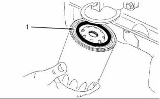
Engine Oil Filter
Spin-on Oil Filter
g00915984
Illustration 24
(1) Seal
g01017012
Note: Lubricate the top of the seal with clean engine
Illustration 23
oil before installation.
Typical example
Type ............................................................. Full flow
(1) Camshaft bearing
The diameter for the installed camshaft
Pressure to open engine oil filter bypass
bearing .............................. 50.787 to 50.848 mm
(1.9995 to 2.0019 inch)
valve ............................. 80 to 120 kPa (12 to 18 psi)
i02801191
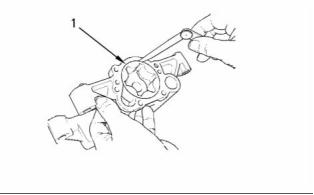
Engine Oil Pump
Three Cylinder Engines without
Balancer Group
Type ............................. Gear-driven differential ro
This document has been printed from SPI². Not for Resale
![]()
![]()
![]()
16
KENR6911
Specifications Section
Number of lobes
Inner rotor ......................................................... 5
Outer rotor ........................................................ 6
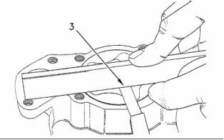
g00938799
Illustration 27
Checking the end play
(3) End play of rotor assembly
g00938064
Illustration 25
Inner rotor ............................. 0.038 to 0.089 mm
(0.0014 to 0.0035 inch)
The oil pump
(1) Clearance of the outer rotor to the
body ...................................... 0.152 to 0.330 mm
(0.0059 to 0.0129 inch)
Outer rotor ............................ 0.025 to 0.076 mm
(0.0010 to 0.0029 inch)
Tighten the bolts that hold the front cover of the oil
pump assembly to the following torque. ........ 26 N·m
(19 lb ft)
i02807662
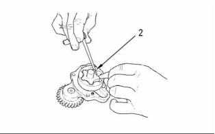
Engine Oil Pressure
g00938061
Illustration 26
Checking the clearance
The minimum oil pressure at the maximum engine
speed and at normal operating temperature is the
following value. ............................... 300 kPa (43 psi)
(2) Clearance of inner rotor to outer
rotor ...................................... 0.040 to 0.127 mm
(0.0015 to 0.0050 inch)
This document has been printed from SPI². Not for Resale
![]()
![]()
![]()
![]()
KENR6911
17
Specifications Section
i02807665
i02807666
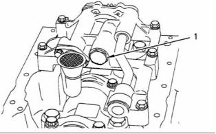
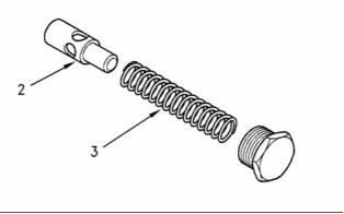
Engine Oil Bypass Valve
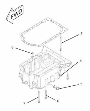
Engine Oil Pan
Installed in the Oil Pump
Table 6
Required Tools
Tool
Part Number
Part Description
Qty
POWERPART Rubber
Sealant
A
21826038
1
POWERPART
Threadlock and
Nutlock
B
21820117
1
Front sealant
g00919893
Illustration 28
Typical example
g00990254
Illustration 30
Applying sealant
(1) Apply Tooling (A) to the cylinder block and to the
timing case.
g00921377
Note: Apply a sealant bead of 3.5 mm (0.1378 inch)
that is shown in illustration 30.
Illustration 29
(2) Plunger
(3) Spring
Rear sealant
(1) Tighten the plug for the relief valve to the
following torque. ....................... 35 N·m (26 lb ft)
Note: Install the rear oil seal before sealant is applied
to the bridge.
(2) Plunger
Diameter of the plunger ..... 19.186 to 19.211 mm
(0.7554 to 0.7563 inch)
Clearance of plunger in bore .. 0.039 to 0.114 mm
(0.0015 to 0.0045 inch)
This document has been printed from SPI². Not for Resale
![]()
![]()
![]()

![]()
18
KENR6911
Specifications Section
(6) Tighten the remaining bolts to the following
torque. ...................................... 22 N·m (16 lb ft)
Note: The rear face of the cast iron oil pan must be
aligned to the rear face of the cylinder block.
The maximum allowed value of the rear face
misalignment. .......................... 0.1 mm (0.0039 inch)
Note: The sealant is applied to new bolts. In order to
reuse the bolts, apply Tooling (B) to the first three
threads of the used bolts.
(5) Tighten the drain plug for the engine oil pan to
the following torque. ................. 34 N·m (25 lb ft)
g00990255
Illustration 31
Applying sealant
(8) Tighten the nut for the dipstick (not shown) to the
following torque. ....................... 18 N·m (13 lb ft)
(2) ApplyTooling (A) to the bridge. The sealant must
not protrude more than 5 mm (0.1969 inch)
above the bridge.
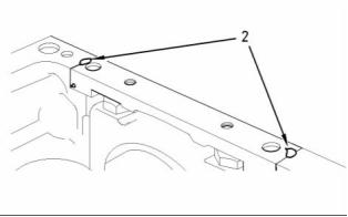
i02807667
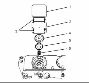
Crankcase Breather
Note: The oil pan must be installed within 10 minutes
of applying the sealant.
Table 7
Required Tools
Tool
Part Number
Part Description
Qty
POWERPART Rubber
Grease
A
21820221
1
g01236729
Illustration 32
Tighten the two nuts (4) to the studs (3).
Tighten the two nuts (4) to the following
torque. ............................................. 11 N·m (97 lb in)
(7) Tighten the four front bolts to the following
torque. ...................................... 22 N·m (16 lb ft)
This document has been printed from SPI². Not for Resale
![]()
![]()
![]()

KENR6911
19
Specifications Section
g01410651
g01410612
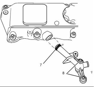
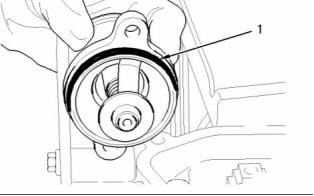
Illustration 33
Breather valve
Illustration 34
(7) O-ring
(1) Plastic cover
(2) Cover plate
(3) Screws
Note: Apply Tooling (A) to the O-ring before installing
the breather pipe in the valve mechanism cover.
(8) Tighten the bolts that secure the breather pipe to
the cylinder head to the following torque. .. 9 N·m
(80 lb in)
Tighten the screws for the cover plate with a
plastic valve mechanism cover to the following
torque. .................................. 1.3 N·m (11.5 lb in)
Tighten the screws for the cover plate with a
metal valve mechanism cover to the following
torque. ..................................... 1.8 N·m (16 lb in)
i02807668
,Water Temperature Regulator
and Housing
(4) Diaphragm
(5) Cap
(6) Spring
Table 8
Required Tools
Tool
Part Number
Part Description
Qty
POWERPART
Rubber Grease
A
21820221
1
Tighten the bolts (not shown) that fasten the housing
to the following torque. .................... 22 N·m (16 lb ft)
This document has been printed from SPI². Not for Resale
![]()
![]()
![]()

20
KENR6911
Specifications Section
g00997234
g00915951
Illustration 35
O ring
Illustration 36
Tightening sequence
Note: Apply Tooling (A) to the O-ring (1) in order to
install the thermostat housing.
Note: Apply Tooling (A) to the first three threads of
the bolts before installation.
Opening temperature ............................ 79 ° to 84 °C
(174 ° to 151 °F)
Tighten the nine bolts that secure the water pump to
the front housing in the numerical sequence that is
shown to the following torque. ........ 22 N·m (16 lb ft)
Full opening temperature ................... 93 °C (199 °F)
Note: Refer to the Disassembly and Assembly
Minimum stroke at full open temperature ........ 9 mm
(0.3937 inch)
Manual in order to service the water pump.
i02807670
i02807669
Cylinder Block
Water Pump
Table 10
Required Tools
Part
Tool
A
Part Name
Qty
Number
21826038
Silicone Sealant
1
Table 9
Required Tools
Part
Tool
A
Part Name
Qty
Number
21820117
Thread Lock
1
This document has been printed from SPI². Not for Resale
![]()
![]()

![]()

KENR6911
21
Specifications Section
Bore in the cylinder block for the main
bearings ............................ 80.416 to 80.442 mm
(3.1660 to 3.1670 inch)
(12) Main bearing cap bolts for the four cylinder and
three cylinder engines
Use the following procedure in order to install the
main bearing cap bolts:
1. Apply clean engine oil to the threads of the main
bearing cap bolts.
2. Put the main bearing caps in the correct position
that is indicated by a number on the top of the
main bearing cap. Install the main bearing caps
with the locating tabs in correct alignment with the
recess in the cylinder block.
3. Evenly tighten the main bearing cap bolts.
Torque for the main bearing cap bolts. .... 245 N·m
(180 lb ft)
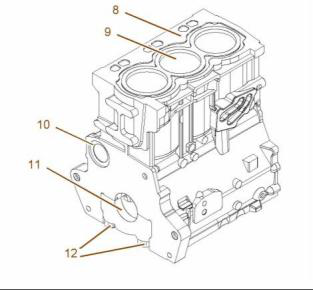
g01018250
Illustration 37
Typical example
(8) Cylinder block
(9) Cylinder bore ................ 105.000 to 105.025 mm
(4.1338 to 4.1348 inch)
The first oversize bore
diameter .................................. 105.5 to 105.525 mm
(4.1535 to 4.1545 inch)
The second oversize bore
diameter .............................. 106.000 to 106.025 mm
(4.1732 to 4.1742 inch)
The maximum permissible wear for the cylinder bore
................................. 0 to 0.15 mm (0 to 0.0059 inch)
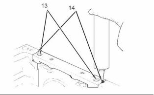
g01018262
Illustration 38
Use the following procedure in order to install the
Allen head bolts for the bridge.
(10) Camshaft bearings for the four cylinder engine
Diameter of the bore in the cylinder
block for the number 1 camshaft
bearing .............................. 55.563 to 55.593 mm
(2.1875 to 2.1887 inch)
Note: Install the rear seal before sealant is applied.
1. Use a straight edge in order to ensure that the
bridge is aligned with the rear face of the cylinder
block.
Diameter of the bore in the cylinder
block for the number 2 camshaft
journal ............................... 50.546 to 50.597 mm
(1.9900 to 1.9920 inch)
2. Tighten the Allen head bolts (13) for the bridge.
Torque for the Allen head bolts .. 16 N·m (12 lb ft)
Diameter of the bore in the cylinder
block for the number 3 camshaft
journal ............................... 50.546 to 50.597 mm
(1.9900 to 1.9920 inch)
3. When the bridge is installed on the cylinder block,
applyTooling (A) into groove (14) at each end of
the bridge. Apply the sealant into the groove until
the sealant is forced through the bottom end of
the groove in the bridge.
Diameter of the bore in the cylinder
block for the number 4 camshaft
journal ............................... 50.038 to 50.089 mm
(1.9700 to 1.9720 inch)
Total height of the cylinder block between the top and
the bottom faces. ................ 441.173 to 441.274 mm
(17.3689 to 17.3729 inch)
(11) Main bearings for the three cylinder engine
This document has been printed from SPI². Not for Resale
![]()
![]()
![]()
22
KENR6911
Specifications Section
i02807671
Crankshaft
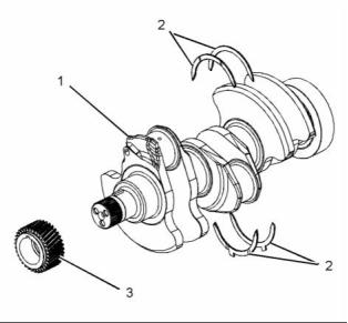
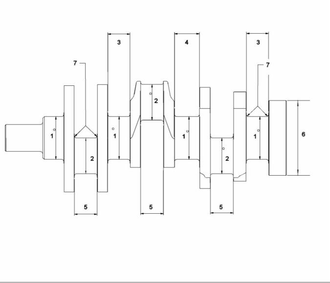
g01427697
Illustration 39
The crankshaft for the three cylinder engine
(1) Crankshaft for the three cylinder engine
The maximum end play of the crankshaft ... 0.51 mm
(0.0201 inch)
(2) Thrust washers
Standard thickness ................... 2.26 to 2.31 mm
(0.089 to 0.091 inch)
Oversize thickness ................... 2.45 to 2.50 mm
(0.097 to 0.098 inch)
(3) The crankshaft gear
Maximum permissible temperature of the gear for
installation on the crankshaft ........... 180 °C (356 °F)
Note: The timing mark is toward the outside of
the crankshaft when the gear is installed on the
crankshaft.
Note: All fillets on the 1103D engines are induction
hardened. No additional hardening is required when
the crankshaft has been reground.
This document has been printed from SPI². Not for Resale
![]()
![]()
KENR6911
23
Specifications Section
g01017747
Illustration 40
The crankshaft for the three cylinder engine
The crankshaft for the three Cylinder engine
This document has been printed from SPI². Not for Resale
![]()
![]()
24
KENR6911
Specifications Section
Table 11
The undersize diameter of the Crankshaft Journals
NUMBER
0.25 mm (0.010 inch)
0.51 mm (0.020 inch)
0.76 mm (0.030 inch)
75.926 mm (2.9892 inch) to
75.905 mm (2.9884 inch)
75.672 mm (2.9792 inch) to
75.651 mm (2.9784 inch)
75.418 mm (2.9692 inch) to
75.397 mm (2.9684 inch)
1
63.236 mm (2.4896 inch) to
63.216 mm (2.4888 inch)
62.982 mm (2.4796 inch) to
62.962 mm (2.4788 inch)
62.728 mm (2.4696 inch) to
62.708 mm (2.4688 inch)
2
3
4
5
6
7
39.47 mm
(1.5539 inch)maximum
N/A
N/A
N/A
N/A
N/A
N/A
N/A
N/A
N/A
N/A
44.68 mm
(1.7591 inch)maximum
40.551 mm
(1.5965 inch)maximum
133.17 mm (5.2429 inch) Do
not machine this diameter.
3.68 mm (0.1449 inch) to
3.96 mm (0.1559 inch)
Refer to table 12 for the maximum run out of the
crankshaft journals.
i02847193
Crankshaft Seals
The maximum difference in value between one
crankshaft journal and the next crankshaft journal
............................................... 0.10 mm (0.0039 inch)
Table 12
Journal
(1)
Excessive run out
Mounting Dia
(2)
0.08 mm (0.0031 inch)
0.08 mm (0.0031 inch)
Mounting Dia
(3)
(4)
Refer to the Specifications Module, “Connecting Rod
Bearing Journal” topic for more information on the
connecting rod bearing journals and connecting rod
bearings.
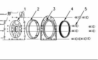
g00915078
Illustration 41
Refer to the Specifications Module, “Main Bearing
Journal” topic for information on the main bearing
journals and for information on the main bearings.
(1) Crankshaft
(2) Plastic sleeve
(3) Crankshaft seal
(4) Alignment tool
This document has been printed from SPI². Not for Resale
![]()


![]()
KENR6911
25
Specifications Section
i02807674
Main Bearing Journal
Refer to Specifications Manual, “Crankshaft” for
information on the undersize main bearing journals,
and information on the width of main bearing journals.
The original size of the main bearing
journal ..................................... 76.159 to 76.180 mm
(2.9984 to 2.9992 inch)
Maximum permissible wear of the main bearing
journals ............................... 0.040 mm (0.0016 inch)
Radius of the fillet of the main bearing
journals ..... 3.68 to 3.69 mm (0.1448 to 0.1452 inch)
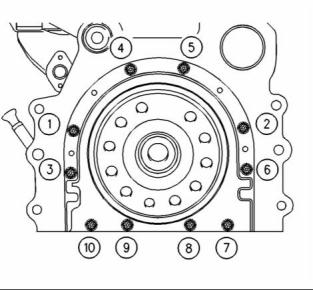
g00915076
Illustration 42
Surface finish of bearing journals, crank pins and
radii ................................... 0.4 microns (16 µ inches)
(5) Tighten bolts 1, 2, 3, 4, 5, 6, 7, and 10 in the
sequence that is shown in Illustration 42 to the
following torque. ....................... 22 N·m (16 lb ft)
The shell for the main bearings
The shells for the main bearings are available
for remachined journals which have the following
undersize dimensions.
Remove the alignment tool.
Tighten bolts 8 and 9 in the sequence that is shown
in Illustration 42 to the following torque. ........ 22 N·m
(16 lb ft)
Undersize bearing shell .... 0.25 mm (0.010 inch)
Undersize bearing shell .... 0.51 mm (0.020 inch)
Undersize bearing shell .... 0.75 mm (0.030 inch)
i02807673
Connecting Rod Bearing
Journal
Thickness at center of the shells .. 2.083 to 2.089 mm
(0.0820 to 0.0823 inch)
Width of the main bearing shells .. 31.62 to 31.88 mm
(1.244 to 1.255 inch)
Clearance between the bearing shell and the main
bearing journals ........................... 0.057 to 0.117 mm
(0.0022 to 0.0046 inch)
Refer to the Specifications Module, “Crankshaft” topic
for information on the undersize crankshaft journals.
The original size of the connecting rod bearing
journal ... 63.47 to 63.49 mm (2.4988 to 2.4996 inch)
Maximum permissible wear of the connecting rod
bearing journals .................... 0.04 mm (0.0016 inch)
Width of the connecting rod bearing
journals ..... 40.35 to 40.42 mm (1.589 to 1.591 inch)
Radius of the fillet of the connecting rod bearing
journals ......... 3.68 to 3.96 mm (0.145 to 0.156 inch)
Surface finish of connecting rod bearing journals and
radii ................................. Ra 0.4 microns (16 µ inch)
This document has been printed from SPI². Not for Resale
![]()
![]()
26
KENR6911
Specifications Section
i02807675
Connecting Rod
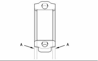
g00995584
Illustration 44
Alignment of the bearing shell
Note: The bearing shell for the connecting rod
must be aligned equally from both ends of the
connecting rod. Refer to (A) in figure 44. Refer to the
Disassembly and assembly manual for information
on the alignment tool.
Table 13
Bearing Width for the
Connecting Rod
31.62 to 31.88 mm
(1.245 to 1.255 inch)
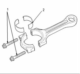
g00907738
Bearing Width for the
Connecting Rod Cap
31.62 to 31.88 mm
(1.245 to 1.255 inch)
Illustration 43
The mating surfaces of the connecting rod are
produced by hydraulically fracturing the forged
connecting rod.
Thickness of Connecting
Rod Bearing at the
Center
1.835 to 1.842 mm
(0.0723 to 0.0725 inch)
Thickness of Connecting
Rod Bearing for the Cap
at the Center
(1) Tighten the torx screws for the connecting rod to
the following torque. ................. 18 N·m (13 lb ft)
1.835 to 1.842 mm
(0.0722 to 0.0725 inch)
Tighten the torx screws for the connecting rod again
to the following torque. .................... 70 N·m (52 lb ft)
0.030 to 0.081 mm
(0.0012 to 0.0032 inch)
Bearing Clearance
Tighten the torx screws for the connecting rod for
an additional 120 degrees. The torx screws for
the connecting rod (1) must be replaced after this
procedure.
Table 14
Undersized Connecting Rod Bearing
0.25 mm (0.010 inch)
0.51 mm (0.020 inch)
0.76 mm (0.030 inch)
Note: Always tighten the connecting rod cap to the
connecting rod, when the assembly is out of the
engine. Tighten the assembly to the following torque
20 N·m (14 lb ft).
(2) The bearing shell for the connecting rod
This document has been printed from SPI². Not for Resale
![]()
![]()
![]()


KENR6911
27
Specifications Section
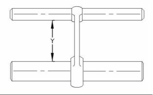
Table 15
Length Grades for Connecting Rods
Grade Letter Color Code
Length (Y)
165.728 to 165.761 mm
(6.5247 to 6.5260 inch)
F
G
H
J
Red
Orange
White
Green
Purple
Blue
165.682 to 165.715 mm
(6.5229 to 6.5242 inch)
165.637 to 165.670 mm
(6.5211 to 6.5224 inch)
165.591 to 165.624 mm
(6.5193 to 6.5206 inch)
165.545 to 165.578 mm
(6.5175 to 6.5188 inch)
K
L
165.499 to 165.532 mm
(6.5157 to 6.4961 inch)
i02807676
Piston and Rings
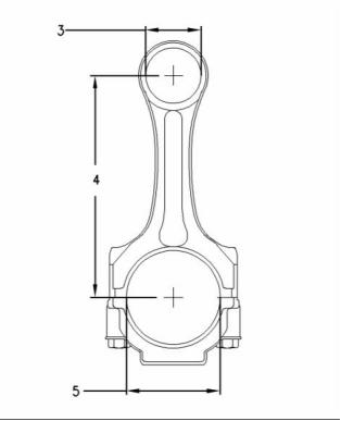
g00907744
Illustration 45
(3) Diameter of the parent bore for the piston
pin ....... 43.01 to 43.04 mm (1.693 to 1.694 inch)
(4) Distance between the parent bores
........ 219.05 to 219.10 mm (8.624 to 8.626 inch)
(5) Diameter for the parent bore for the connecting
rod bearing ........................... 67.21 to 67.22 mm
(2.6460 to 2.6465 inch)
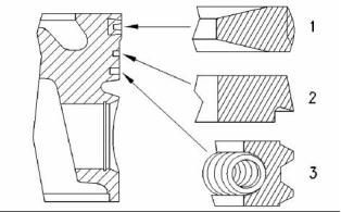
g00888215
Illustration 47
A typical example of a piston and rings
(1) Top compression ring
Naturally Aspirated
The shape of the top compression
ring ...................... Rectangular with a barrel face
Width of the top compression
ring ........ 2.475 to 2.49 mm (0.097 to 0.098 inch)
g00915056
Clearance between the top compression ring and
the piston groove ........................ 0.09 to .15 mm
(0.0035 to 0.0059 inch)
Illustration 46
Connecting rods are color coded. The color code
is a reference for the length (Y) of the connecting
rod. Refer to table 15 for the different lengths of
connecting rods.
Ring gap ................................... 0.30 to 0.55 mm
(0.0118 to 0.0216 inch)
Turbocharged
The shape of the top compression
ring ........................... Keystone with a barrel face
This document has been printed from SPI². Not for Resale
![]()
![]()
![]()

![]()
28
KENR6911
Specifications Section
Width of the top compression ring .......... tapered
The combustion bowl re-entrant angle for the
turbocharged engine ............................... 80 degrees
Ring gap ................................... 0.30 to 0.55 mm
(0.0118 to 0.0216 inch)
The combustion bowl re-entrant angle for the
naturally aspirated engine ....................... 70 degrees
Note: When you install a new top compression ring,
make sure that the word “TOP” is facing the top of the
piston. New top piston rings have a red identification
mark which must be on the left of the ring end gap
when the top piston ring is installed on an upright
piston.
Piston height above cylinder block .. 0.21 to 0.35 mm
(0.008 to 0.014 inch)
Width of top groove in piston for the naturally
aspirated engine ............................. 2.58 to 2.60 mm
(0.1016 to 0.1024 inch)
(2) Intermediate compression ring
Width of top groove in piston for the turbocharged
engine .......................................................... Tapered
The shape of the intermediate compression
ring ......................................... Internal step in the
bottom edge with a tapered face
Width of second groove in piston .... 2.54 to 2.56 mm
(0.1000 to 0.1008 inch)
Width of intermediate compression
ring .......... 2.47 to 2.49 mm (0.097 to 0.098 inch)
Width of third groove in piston ........ 3.52 to 3.54 mm
(0.1386 to 0.1394 inch)
Clearance between the intermediate compression
ring and the piston groove ........ 0.05 to 0.09 mm
(0.002 to 0.003 inch)
Piston pin
Ring gap ................................... 0.70 to 0.95 mm
(0.0275 to 0.0374 inch)
Diameter of a new piston
pin ..................................... 39.694 to 39.700 mm
(1.5628 to 1.5630 inch)
Note: When you install a new intermediate
compression ring, make sure that the word “TOP” is
facing the top of the piston. New intermediate rings
have a green identification mark which must be on
the left of the ring end gap when the top piston ring is
installed on an upright piston.
Diameter of the bore for the piston
pin ..................................... 39.703 to 39.709 mm
(1.5631 to 1.5633 inch)
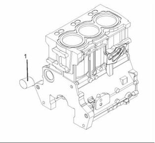
i02807678
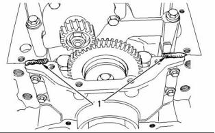
Piston Cooling Jet
(3) Oil control ring
Shape of oil control
ring .............. Two-piece coil that is spring loaded
Width of oil control ring ............. 3.47 to 3.49 mm
(0.1366 to 0.1374 inch)
Note: The three cylinder naturally aspirated engine
may have installed piston cooling jets as an option.
Clearance between the oil control ring and the
groove in the piston .................. 0.03 to 0.07 mm
(0.0011 to 0.0027 inch)
Ring gap ................................... 0.30 to 0.55 mm
(0.0118 to 0.0216 inch)
Note: A pin is used in order to hold both ends of the
spring of the oil control ring in position. The ends of
the spring of the oil control ring must be installed
opposite the end gap of the oil control ring.
Note: Ensure that the ring end gaps of the piston
rings are spaced 120 degrees from each other.
Piston
g00942652
Illustration 48
Note: An arrow which is marked on the piston crown
must be toward the front of the engine.
(1) Installed piston cooling jets
This document has been printed from SPI². Not for Resale
![]()
![]()
KENR6911
29
Specifications Section
The valve that is spring loaded must move freely.
Tighten the bolt to the following torque. ........... 9 N·m
(7 lb ft)
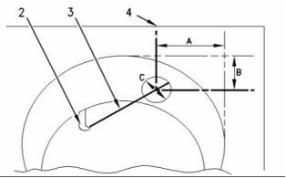
Piston Cooling Jet Alignment
g01224872
Illustration 50
Alignment
(1) Tighten the bolts that fasten the front cover to the
front housing to the following torque. ....... 22 N·m
(16 lb ft)
g01006929
Illustration 49
(2) Piston cooling jet
(3) Rod
(4) Cylinder block
Use the following procedure in order to check the
alignment of the piston cooling jet.
1. Insert rod (3) into the end of the piston cooling
jet (2). Rod (3) has a diameter of 1.70 mm
(0.067 inch). Rod (3) must protrude out of the top
of the cylinder block.
2. Dimension (A) is 55.25 mm (2.1752 inch) and
dimension (B) is 14 mm (0.5512 inch). Dimension
(A) and dimension (B) are tangent to the cylinder
bore (4).
3. The position of the rod (3) must be within
dimension (C). Dimension (C) is 14 mm
(0.5512 inch).
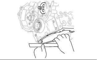
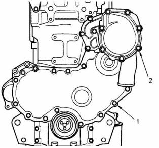
g00918672
Illustration 51
i02807679
Front cover
Front Housing and Covers
(2) Tighten the bolts that fasten the water pump to the
front housing to the following torque. ....... 22 N·m
(16 lb ft)
Note: Refer to Specifications, “Water Pump” for the
correct bolt tightening sequence for the water pump.
The front housing must be aligned to the cylinder
block face. ................................. + 0.05 to minus 0.05
mm (+ 0.0020 to minus 0.0020 inch )
This document has been printed from SPI². Not for Resale
![]()
![]()
![]()
![]()
30
KENR6911
Specifications Section
i02807680
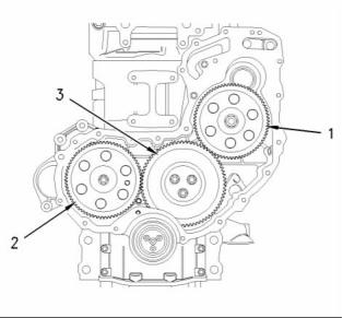
Number of teeth .............................................. 68
(3) Idler gear and hub
Gear Group (Front)
Tighten the bolts for the idler gear to the following
torque. ...................................... 44 N·m (33 lb ft)
Bore diameter of the idler gear
The 1103D mechanical engine may use two types
of fuel injection pump. The fuel injection pump may
be a Delphi 210 fuel injection pump or a Delphi 310
fuel injection pump.
.... 57.137 to 57.175 mm (2.2495 to 2.2510 inch)
Bore diameter of the idler gear with roller
bearings ............................ 72.345 to 72.364 mm
(2.8482 to 2.8490 inch)
Width of idler gear and split bearing
assembly .......................... 30.135 to 30.165 mm
(1.186 to 1.188 inch)
Inside diameter of idler gear bearings with
flanges .............................. 50.797 to 50.818 mm
(1.9999 to 2.0007 inch)
Outside diameter of idler gear
hub .................................... 50.716 to 50.737 mm
(1.9967 to 1.9975 inch)
Outside diameter of idler gear hub with roller
bearings ............................. 59.100 to 59.115 mm
(2.3268 to 2.3274 inch)
Idler gear end play .................... 0.10 to 0.20 mm
(0.004 to 0.008 inch)
Maximum permissible end play ............ 0.38 mm
(0.015 inch)
Idler gear end play with roller
g00995886
bearings .................................... 0.10 to 0.75 mm
(0.0039 to 0.0295 inch)
Illustration 52
Gear train
Number of teeth .............................................. 73
(1) Fuel injection pump drive gear
Tighten the nut to the following torque. ... 24 N·m
(18 lb ft)
Release the lock on the fuel injection pump shaft.
Torque the nut to the following torque. .... 90 N·m
(66 lb ft)
Number of teeth .............................................. 68
Note: Refer to the Specifications, “Fuel Injection
Pump” for the locking torque for the fuel injection
pump shaft.
(2) Camshaft gear
Tighten the bolt for the camshaft gear to the
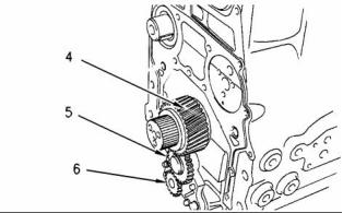
g00996214
Illustration 53
following torque. ....................... 95 N·m (70 lb ft)
The gear train for the oil pump
Bore diameter of the camshaft
gear ...................................... 34.92 to 34.95 mm
(1.3748 to 1.3760 inch)
(4) Crankshaft gear
Bore diameter of crankshaft gear
.... 47.625 to 47.650 mm (1.8750 to 1.8760 inch)
Outside diameter of the camshaft
hub .. 34.90 to 34.92 mm (1.3741 to 1.3747 inch)
This document has been printed from SPI². Not for Resale
![]()
![]()
![]()
KENR6911
31
Specifications Section
Outside diameter of crankshaft
i02807681
hub .................................... 47.625 to 47.645 mm
(1.8750 to 1.8758 inch)
Flywheel
Clearance of gear on
crankshaft ......................... −0.020 to +0.025 mm
(−0.0008 to +0.0010 inch)
Number of teeth .............................................. 34
(5) Oil pump idler gear
Inside diameter of oil pump idler gear
bearing .............................. 16.012 to 16.038 mm
(0.6304 to 0.6314 inch)
Outside diameter of oil pump idler gear
shaft .................................. 15.966 to 15.984 mm
(0.6286 to 0.6293 inch)
Clearance of oil pump idler gear bearing on
shaft ...................................... 0.028 to 0.072 mm
(0.0011 to 0.0028 inch)
End play of the oil pump idler
gear ...................................... 0.050 to 0.275 mm
(0.0019 to 0.0108 inch)
(6) Oil pump gear
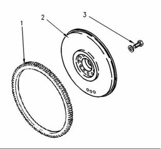
g00584712
Illustration 54
The number of teeth on the oil pump gear ..... 17
Standard flywheel
Backlash values
(1) Flywheel ring gear
Backlash between the idler gear (5) and the oil
pump drive gear (6) .............. 0.046 to 0.106 mm
(0.0018 to 0.0041 inch)
Heat the flywheel ring gear to the following
temperature. .............................. 250 °C (480 °F)
Backlash between the oil pump idler gear (5) and
the crankshaft gear (4) ......... 0.095 to 0.160 mm
(0.0037 to 0.0063 inch)
Note: Do not use an oxyacetylene torch to heat the
flywheel ring gear.
(2) Flywheel
(3) Bolt
Backlash between the idler gear (3) and the
crankshaft gear (4) ............... 0.064 to 0.124 mm
(0.0025 to 0.0049 inch)
Tighten the flywheel bolts to the following
torque. ..................................... 115 N·m (85 lb ft)
Backlash between the camshaft gear (2) and the
idler gear (3) ......................... 0.052 to 0.107 mm
(0.0020 to 0.0042 inch)
Non-standard flywheel
Backlash between the fuel injection pump gear
(1) and the idler gear (3) ....... 0.054 to 0.109 mm
(0.0021 to 0.0043 inch)
Note: A special flywheel is aligned to a dowel on the
crankshaft.
Backlash between the water pump gear (not
shown) and the fuel injection pump gear
(1) ... 0.073 to 0.133 mm (0.0028 to 0.0052 inch)
Backlash between the power take-off
drive ( if equipped) and the idler gear
(3) .... 0.112 to 0.172 mm (0.0044 to 0.0068 inch)
This document has been printed from SPI². Not for Resale
![]()
![]()
32
KENR6911
Specifications Section
i02807682
i02807684
Flywheel Housing
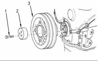
Crankshaft Pulley
g00915497
Illustration 56
Typical example
(1) Tighten the three bolts progressively for
the crankshaft pulley to the following
torque. ..................................... 115 N·m (85 lb ft)
Note: Recheck the torque of the bolts (1) twice.
(2) Thrust block
(3) Crankshaft pulley
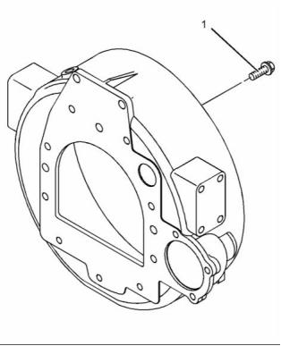
g01338247
Illustration 55
i02830701
Typical example
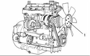
Fan Drive
(1) Bolt
Tighten the bolts for the flywheel housing to the
following torque:
M10 “8.8” .................................. 44 N·m (33 lb ft)
M10 “10.9” ................................ 63 N·m (47 lb ft)
M12 “8.8” .................................. 75 N·m (55 lb ft)
M12 “10.9” ............................... 115 N·m (85 lb ft)
Tighten the studs (not shown) that support the
extension for the fan to 11 N·m (8 lb ft).
Note: Certain engines may be equipped with a back
plate.
This document has been printed from SPI². Not for Resale
![]()
![]()
![]()
KENR6911
33
Specifications Section
i02807693
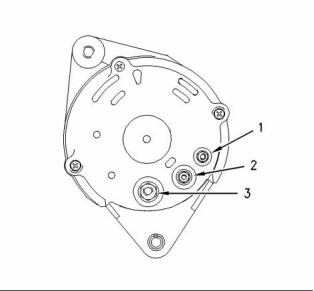
Alternator
12 Volt Alternator
g00926178
Illustration 57
A typical fan drive
(1) Tighten the nuts for the fan to the following
torque. ...................................... 22 N·m (16 lb ft)
Fan drive housing
Tighten the bolts that secure the fan drive housing
to the cylinder head to the following torque (not
shown). ........................................... 44 N·m (32 lb ft)
Maximum permissible end play of the shaft .. 0.20 mm
(0.0079 inch)
g00959541
Illustration 58
i02807686
A typical alternator
Engine Lifting Bracket
(1) Tighten terminal nut “W” to the following
torque. ........................................ 2 N·m (17 lb in)
(2) Tighten terminal nut “D+” to the following
torque. ..................................... 4.3 N·m (38 lb in)
All engines are equipped with two engine lifting
brackets.
(3) Tighten terminal nut “B+” to the following
torque. ..................................... 4.3 N·m (38 lb in)
Tighten the two bolts on each engine lifting
bracket to the following torque. .. 44 N·m (32 lb ft)
Tighten the pulley nut (not shown) to the following
torque. ............................................. 80 N·m (59 lb ft)
Alignment of the alternator pulley to the crankshaft
pulley .............................. ± 2.4 mm ( ± 0.0945 inch)
Rotation .................................................... clockwise
Polarity ............................................... Negative earth
V-Belt
Note: The V-belt must be checked by a gauge. Refer
to Operation and Maintenance Manual, “Alternator
and Fan Belts - Inspect/Adjust/Replace” for the
correct type of gauge in order to check the V-belt.
Initial V-belt tension ........................... 535 N (120 lb)
Used V-belt tension ............................. 355 N (80 lb)
This document has been printed from SPI². Not for Resale
![]()
![]()
![]()
34
KENR6911
Specifications Section
i02807694
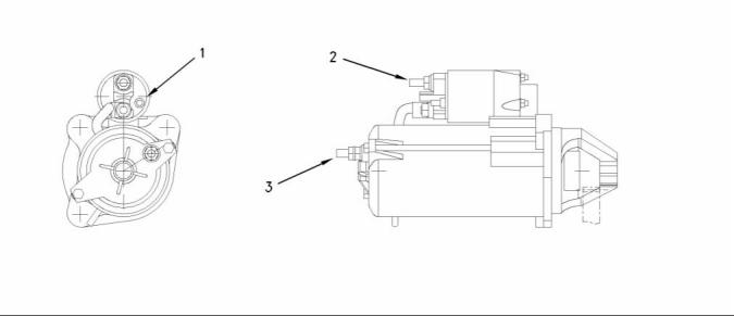
Starter Motor
12 Volt Starting Motor
g00977365
Illustration 59
The 12 volt starting motor which shows the electrical connections
(1) Tighten the solenoid terminal to the following
torque. ....................................... 8 N·m ( 70 lb in)
(2) Tighten the positive terminal nut to the following
torque. ....................................... 6 N·m ( 53 lb in)
(3) Tighten the negative terminal nut to the following
torque. ....................................... 8 N·m (70 lb in)
Rated voltage ................................................ 12 volts
Pull in voltage ................................................. 8 volts
This document has been printed from SPI². Not for Resale
![]()
![]()
KENR6911
35
Specifications Section
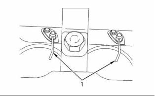
i02807695
Glow Plugs
g01224881
Illustration 60
Typical example
(1) Tighten the glow plugs (3) in the cylinder head to
the following torque. .................. 15 N·m (11 lb ft)
Tighten the nuts (2) for the bus bar (1) that is
installed on top of the glow plugs to the following
torque. ............................................... 2 N·m (18 lb in)
Voltage ................................................. 12 or 24 volts
Note: Glow plugs are not installed on all engines.
Engines that do not have glow plugs are installed
with threaded plugs.
This document has been printed from SPI². Not for Resale
![]()
![]()
Index
A
G
Alternator............................................................... 33
12 Volt Alternator ............................................... 33
V-Belt ................................................................. 33
Gear Group (Front)................................................ 30
Glow Plugs ............................................................ 35
I
C
Important Safety Information.................................
2
7
Camshaft............................................................... 13
Camshaft Bearings................................................ 15
Connecting Rod..................................................... 26
Connecting Rod Bearing Journal........................... 25
Crankcase Breather............................................... 18
Crankshaft ............................................................ 22
Crankshaft Pulley .................................................. 32
Crankshaft Seals................................................... 24
Cylinder Block........................................................ 20
Cylinder Head........................................................ 11
L
Lifter Group............................................................
M
Main Bearing Journal............................................. 25
The shell for the main bearings.......................... 25
Cylinder Head Valves ............................................
8
Naturally Aspirated Engines............................... 10
Turbocharged Engines and Turbocharged
Aftercooled Engines.........................................
8
P
Piston and Rings ................................................... 27
Piston................................................................. 28
Piston Cooling Jet.................................................. 28
Piston Cooling Jet Alignment............................. 29
E
Engine Design.......................................................
4
Engine Lifting Bracket............................................ 33
Engine Oil Bypass Valve ....................................... 17
Installed in the Oil Pump.................................... 17
Engine Oil Filter..................................................... 15
Spin-on Oil Filter ................................................ 15
Engine Oil Pan....................................................... 17
Front sealant...................................................... 17
Rear sealant....................................................... 17
Engine Oil Pressure............................................... 16
Engine Oil Pump.................................................... 15
Three Cylinder Engines without Balancer
R
Rocker Shaft..........................................................
7
4
S
Specifications Section ...........................................
Starter Motor.......................................................... 34
Group............................................................... 15
Exhaust Manifold................................................... 13
12 Volt Starting Motor ........................................ 34
T
F
Table of Contents...................................................
Turbocharger......................................................... 12
3
Fan Drive............................................................... 32
Fan drive housing .............................................. 33
Flywheel ................................................................ 31
Non-standard flywheel ....................................... 31
Flywheel Housing.................................................. 32
Front Housing and Covers..................................... 29
V
Valve Mechanism Cover........................................
8
Fuel Injection Lines................................................
Fuel Injection Pump...............................................
Delphi DP210 and Delphi DP310.......................
Fuel Injectors.........................................................
Fuel Transfer Pump...............................................
4
5
5
6
6
W
Water Pump........................................................... 20
Water Temperature Regulator and Housing.......... 19
©2008 Perkins Engines Company Limited
All Rights Reserved
Printed in U. K.
This document has been printed from SPI². Not for Resale
免費熱線
400-100-8969???15088860848
400-100-8969???15088860848
機組銷售
0574-26871589? 15267810868
0574-26871589? 15267810868
配件銷售
0574-26886646? 15706865167
0574-26886646? 15706865167
維修熱線
0574-26871569 18658287286
0574-26871569 18658287286
手機端

微信公眾號