 English
 Espaol
 Franais
 阿拉伯
阿拉伯 中文(簡)
中文(簡) Deutsch
 Italiano
 Português
 日本
日本 韓國
韓國 български
 hrvatski
 esky
esky Dansk
Dansk Nederlands
 suomi
suomi Ελληνικ
 印度
印度 norsk
norsk Polski
 Roman
Roman русский
 Svenska
 珀金斯Perkins1204E-E44TA(TTA)技術(shù)資料,珀金斯Perkins1204E-E44TA(TTA)技術(shù)資料技術(shù)支持中心,珀金斯Perkins1204E-E44TA(TTA)技術(shù)資料代理商,珀金斯Perkins1204E-E44TA(TTA)技術(shù)資料銷售服務(wù)中心,珀金斯Perkins1204E-E44TA(TTA)技術(shù)資料價(jià)格規(guī)格資料查詢,寧波日昕動(dòng)力科技有限公司

首頁
產(chǎn)品展示>珀金斯Perkins1204E-E44TA(TTA)技術(shù)資料(英文)
珀金斯Perkins1204E-E44TA(TTA)技術(shù)資料(英文)
詳細(xì)描述
Specifications
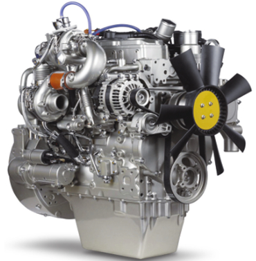
1204E-E44TA and 1204E-E44TTA
Industrial Engines
MK (Engine)
ML (Engine)
This document is printed from SPI². Not for RESALE
![]()
![]()
![]()

Important Safety Information
Most accidents tha t involve produc t op eration, ma intena nc e and repair are caus ed by failure to
ob serve basic safety rules or precautions . An accident can often be avoided by recog nizing pote ntially
ha za rdous situations before an accident oc curs . A person mus t be alert to pote ntial ha za rds. This
person should also ha ve the ne cessary training, skills and tools to perform the se func tions properly.
Improper operation, lubrication, maintenance or repair of this product can be dangerous and
could result in injury or death.
Do not operate or perform any lubrication, maintenance or repair on this product, until you have
read and understood the operation, lubrication, maintenance and repair information.
Sa fety precautions and warning s are provided in this ma nua l and on the produc t. If the se ha za rd
warning s are not he eded, bod ily injury or death could oc cur to you or to othe r persons .
The ha za rds are identified by the “Safety Alert Symb ol” and followed by a “Signa l Word” suc h as
“DANGER”, “WARNING” or “CAUTION”. The Sa fety Alert “WARNING” label is shown below.
The me aning of this safety alert symb ol is as follows:
Attention! Become Alert! Your Safety is Involved.
The me ssage tha t appears und er the warning explains the ha za rd and can be either written or
pictorially presente d.
Op erations tha t ma y caus e produc t dama ge are identified by “NOTICE” labels on the produc t and in
this pub lication.
Perkins cannot anticipate every possible circumstance that might involve a potential hazard. The
warnings in this publication and on the product are, therefore, not all inclusive. If a tool, procedure,
work method or operating technique that is not specifically recommended by Perkins is used,
you must satisfy yourself that it is safe for you and for others. You should also ensure that the
product will not be damaged or be made unsafe by the operation, lubrication, maintenance or
repair procedures that you choose.
The informa tion, specifications , and illustrations in this pub lication are on the basis of informa tion tha t
was available at the time tha t the pub lication was written. The specifications , torque s, pressure s,
me asure me nts , adjustme nts , illustrations , and othe r items can cha ng e at any time. These cha ng es can
affect the service tha t is given to the produc t. Ob tain the comp lete and mos t current informa tion before
you start any job. Pe rkins dealers or Pe rkins distributors ha ve the mos t current informa tion available.
When replacement parts are required for this
product Perkins recommends using Perkins
replacement parts.
Failure to heed this warning can lead to prema-
ture failures, product damage, personal injury or
death.
This document is printed from SPI². Not for RESALE
![]()
![]()
KENR9123-01
3
Table of Contents
Table of Contents
Engine Oil Pressure Sensor ................................. 44
Boost Pressure Sensor ......................................... 45
Atmospheric Pressure Sensor .............................. 45
Inlet Manifold Temperature Sensor ....................... 46
Temperature Sensor (DPF Inlet) ........................... 46
Pressure Sensor (NOx Reduction System) .......... 46
Temperature Sensor (NOx Reduction System) .... 47
Speed/Timing Sensor .......................................... 47
Electronic Control Module ..................................... 48
Glow Plugs ........................................................... 48
Air Compressor (Twin Cylinder Compressor) ....... 49
Air Compressor (Single Cylinder) ......................... 50
Specifications Section
Engine Design .....................................................
Fuel Injection Lines ..............................................
Fuel Injection Pump .............................................
Fuel Injectors .......................................................
Fuel Transfer Pump .............................................
Fuel Filter Base (Single Secondary Fuel Filter
Base) ...................................................................
Fuel Filter Base (Twin Secondary Fuel Filter
Base) ...................................................................
Fuel Filter Base (Primary Fuel Filter Base) ...........
Fuel Manifold (Rail) ...............................................
Lifter Group ...........................................................
Rocker Shaft ........................................................
4
4
5
6
6
7
Index Section
7
8
8
9
9
Index ..................................................................... 51
Valve Mechanism Cover ...................................... 10
Cylinder Head Valves ........................................... 11
Cylinder Head ...................................................... 12
Turbocharger (Series Turbochargers) .................. 13
Turbocharger (Single Turbocharger) .................... 15
Exhaust Gas Valve (NRS) .................................... 17
Exhaust Sensor and Lines (NRS) ......................... 18
Exhaust Cooler (NRS) .......................................... 19
Exhaust Manifold ................................................. 21
Flexible Exhaust Pipe ........................................... 22
Diesel Particulate Filter ......................................... 22
Camshaft ............................................................. 23
Camshaft Bearings .............................................. 24
Engine Oil Filter Base .......................................... 24
Engine Oil Cooler ................................................. 25
Engine Oil Pump .................................................. 25
Engine Oil Pressure ............................................. 26
Engine Oil Pan ..................................................... 26
Crankcase Breather ............................................. 27
Water Temperature Regulator and Housing ......... 28
Water Pump ......................................................... 28
Cylinder Block ...................................................... 29
Crankshaft ........................................................... 29
Crankshaft Seals ................................................. 31
Connecting Rod Bearing Journal ......................... 31
Main Bearing Journal ............................................ 32
Connecting Rod ................................................... 32
Piston and Rings .................................................. 34
Piston Cooling Jet ................................................. 35
Balancer Group .................................................... 35
Accessory Drive (SAE “B”) ................................... 36
Accessory Drive ................................................... 36
Front Housing and Covers ................................... 37
Gear Group (Front) ............................................... 37
Flywheel ............................................................... 39
Flywheel Housing ................................................ 39
Crankshaft Pulley ................................................. 40
Belt Tensioner ....................................................... 40
Refrigerant Compressor ....................................... 41
Fan Drive ............................................................. 41
Engine Lifting Bracket ........................................... 41
Alternator ............................................................. 42
Starter Motor ........................................................ 43
Coolant Temperature Sensor ............................... 44
This document is printed from SPI². Not for RESALE
![]()
4
KENR9123-01
Specifications Section
Specifications Section
When the camshaft is viewed from the front of
the engine, the camshaft rotates in the following
direction: ................................................... Clockwise
i03907589
The front of the engine is opposite the flywheel end.
The left side and the right side of the engine are
viewed from the flywheel end. The No. 1 cylinder is
the front cylinder.
Engine Design
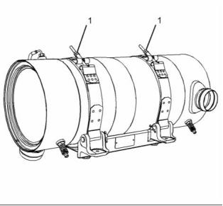
i04136796
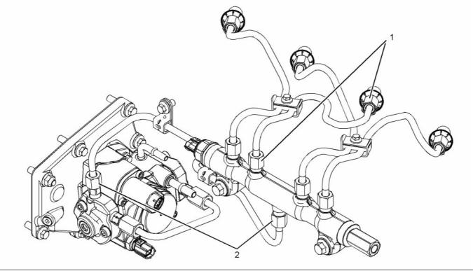
Fuel Injection Lines
Contact with high pressure fuel may cause fluid
penetration and burn hazards. High pressure fu-
el spray may cause a fire hazard. Failure to fol-
low these inspection, maintenance and service in-
structions may cause personal injury or death.
Refer to Operation and Maintenance Manual,
“General Hazard Information and High Pressure Fuel
Lines” before adjustments and repairs are performed.
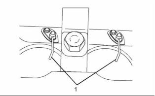
g01335181
NOTICE
Illustration 1
Refer to Systems Operation, Testing, and Adjust-
ing, “Cleanliness of Fuel System Components” for
detailed information on the standards of cleanli-
ness that must be observed during ALL work on
the fuel system.
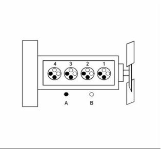
Cylinder and valve location
(A) Exhaust valve
(B) Inlet valve
Bore ......................................... 105 mm (4.133 inch)
Stroke ...................................... 127 mm (5.000 inch)
Ensure that all adjustments and repairs are performed
by authorized personnel that have had the correct
training.
Displacement ...................................... 4.4 L (269 in )
3
Cylinder arrangement ..................................... In-line
Type of combustion ............................ Direct injection
Compression ratio
Turbocharged engines and turbocharged charge
cooled engines ........................................ 16.2:1
Number of cylinders ................................................ 4
Valves per cylinder .................................................. 4
Firing order ................................................. 1, 3, 4, 2
When the crankshaft is viewed from the front of
the engine, the crankshaft rotates in the following
direction: ................................................... Clockwise
This document is printed from SPI². Not for RESALE
![]()
![]()
![]()
![]()
![]()
![]()
KENR9123-01
5
Specifications Section
g02334261
Illustration 2
Typical example
(1), (2) Torque for the nuts on the high-pressure fuel
lines .......................................... 40 N·m (30 lb ft)
i04138513
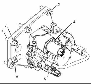
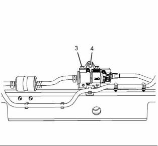
Fuel Injection Pump
Note: The timing of the fuel injection pump will need
to be checked by trained personnel. In order to check
the timing of the fuel injection pump, refer to Systems
Operation, Testing, and Adjusting, “Fuel Injection
Pump Timing - Check”.
NOTICE
Refer to Systems Operation, Testing, and Adjust-
ing, “Cleanliness of Fuel System Components” for
detailed information on the standards of cleanli-
ness that must be observed during ALL work on
the fuel system.
g02335956
Illustration 3
Typical example
(1) Tighten the studs to the following torque. .. 11 N·m
(97 lb in)
(2) Tighten the mounting nut to the following
torque. ...................................... 22 N·m (16 lb ft)
(3) Tighten the setscrews to the following
torque. ...................................... 22 N·m (16 lb ft)
This document is printed from SPI². Not for RESALE
![]()
![]()
![]()
![]()
![]()
6
KENR9123-01
Specifications Section
(4) Tighten the screws for the suction control valve
to the following torque. ............... 9 N·m (80 lb in)
i04139569
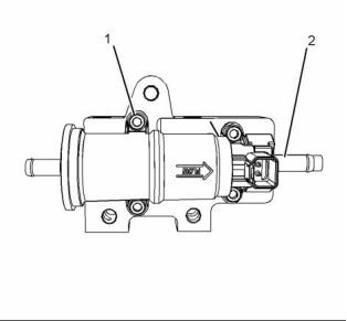
Fuel Transfer Pump
(5) Tighten the fuel temperature sensor to the
following torque. ....................... 22 N·m (16 lb ft)
(6) Tighten the screw to the following
torque. ...................................... 14 N·m (10 lb ft)
i03631793
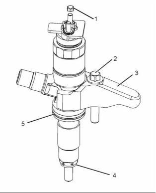
Fuel Injectors
NOTICE
Refer to Systems Operation, Testing and Adjust-
ing, “Cleanliness of Fuel System Components” for
detailed information on the standards of cleanli-
ness that must be observed during ALL work on
the fuel system.
g02337197
Illustration 5
Typical example
(1) Tighten the allen head screws to the following
torque. ........................................ 9 N·m (80 lb in)
(2) Tighten the connection to the following
torque. ...................................... 20 N·m (15 lb ft)
g01862457
Illustration 4
Typical example
(3) Clamp
(4) Washer
(5) O ring seal
g02337198
Illustration 6
(1) Torque for the nuts ...................... 2 N·m (18 lb in)
Typical example
(2) Torque for the bolt in the clamp for the fuel
injection nozzle ...................... 21 N·m (15.5 lb ft)
(3), (4) Tighten the bolts to the following
torque. ...................................... 22 N·m (16 lb ft)
This document is printed from SPI². Not for RESALE
![]()
![]()
![]()
![]()
![]()
![]()
KENR9123-01
7
Specifications Section
i04325509
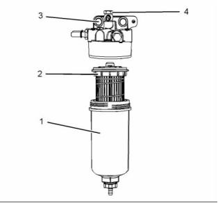
i04330369
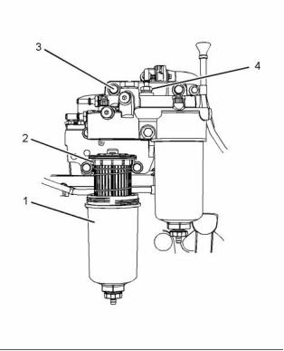
Fuel Filter Base
(Single Secondary Fuel Filter
Base)
Fuel Filter Base
(Twin Secondary Fuel Filter
Base)
NOTICE
NOTICE
Refer to Systems Operation, Testing and Adjust-
ing, “Cleanliness of Fuel System Components” for
detailed information on the standards of cleanli-
ness that must be observed during ALL work on
the fuel system.
Refer to Systems Operation, Testing and Adjust-
ing, “Cleanliness of Fuel System Components” for
detailed information on the standards of cleanli-
ness that must be observed during ALL work on
the fuel system.
If necessary, install a new fuel filter (2) to canister (1).
Refer to Operation and Maintenance Manual, “Fuel
System Secondary Filter - Replace” for the correct
procedure.
If necessary, install a new fuel filter (2) to canister (1).
Refer to Operation and Maintenance Manual, “Fuel
System Secondary Filter - Replace” for the correct
procedure.
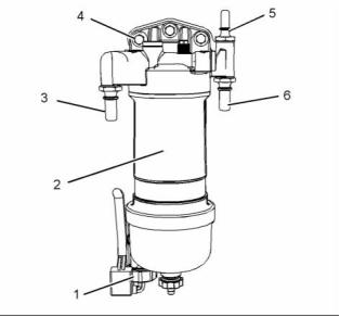
g02484376
Illustration 7
Typical example
(3) Tighten the bolts to the following torque. .. 44 N·m
(33 lb ft)
(4) Tighten the bolt to the following torque. ... 17 N·m
(13 lb ft)
g02485877
Illustration 8
Typical example
(3) Tighten the bolts to the following torque. .. 44 N·m
(33 lb ft)
(4) Tighten the bolt to the following torque. ... 20 N·m
(15 lb ft)
This document is printed from SPI². Not for RESALE
![]()
![]()
![]()
![]()
![]()
![]()
![]()
8
KENR9123-01
Specifications Section
i04363635
i04139570
Fuel Filter Base
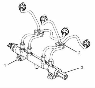
Fuel Manifold (Rail)
(Primary Fuel Filter Base)
Refer to Operation and Maintenance Manual,
“General Hazard Information and High Pressure Fuel
Lines” before adjustments and repairs are performed.
NOTICE
Refer to Systems Operation, Testing and Adjust-
ing, “Cleanliness of Fuel System Components” for
detailed information on the standards of cleanli-
ness that must be observed during ALL work on
the fuel system.
NOTICE
Refer to Systems Operation, Testing and Adjust-
ing, “Cleanliness of Fuel System Components” for
detailed information on the standards of cleanli-
ness that must be observed during ALL work on
the fuel system.
If necessary, install a new fuel filter element to
canister (2). Refer to Operation and Maintenance
Manual, “Fuel System Primary Filter (Water
Separator) Element - Replace” for the correct
procedure.
g02337196
Illustration 10
Typical example
g02289936
(1) Tighten the bolts to the following torque. .. 22 N·m
(16 lb ft)
Illustration 9
Typical example
(2) Tighten the bolts to the following torque. .. 10 N·m
(89 lb in)
Tighten water in fuel switch (1) hand tight.
(3) Tighten the connection to the following
torque. ...................................... 17 N·m (13 lb ft)
(3) Tighten the fuel pressure relief valve to the
following torque. ....................... 30 N·m (22 lb ft)
(4) Tighten the bolts to the following torque. .. 44 N·m
(32 lb ft)
Note: The fuel pressure relief valve (3) should be
tightened an additional 24 degrees.
(5) Tighten the connection to the following
torque. ...................................... 17 N·m (13 lb ft)
(6) Tighten the connection to the following
torque. ...................................... 17 N·m (13 lb ft)
This document is printed from SPI². Not for RESALE
![]()
![]()
![]()
![]()
![]()
![]()
![]()
KENR9123-01
9
Specifications Section
i04381710
i03916469
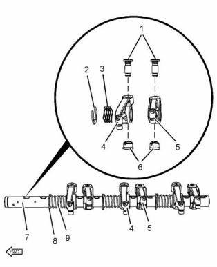
Lifter Group
Rocker Shaft
g01344742
Illustration 11
Typical example
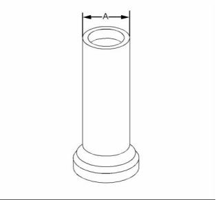
(A) Diameter of the lifter body .. 21.938 to 21.963 mm
(0.86370 to 0.86468 inch)
Bore diameter in the cylinder block
...... 22.000 to 22.032 mm (0.86614 to 0.86740 inch)
g02150799
Illustration 12
Typical example
Clearance
(1) Tighten the threaded inserts to the following
torque. ...................................... 30 N·m (22 lb ft)
Clearance of the lifter .......... 0.038 to 0.095 mm
(0.0015 to 0.0037 inch)
(2) Retaining clip
(3) Spring
(4) Inlet rocker arm
Diameter of the rocker arm bore
.... 25.013 to 25.051 mm (0.9848 to 0.9863 inch)
(5) Exhaust rocker arm
Diameter of the rocker arm bore
.... 25.013 to 25.051 mm (0.9848 to 0.9863 inch)
Clearance
Maximum clearance of both the rocker arm
bores. ............................ 0.089 mm (0.0035 inch)
The service limit for both rocker arm
bores ............................... 0.17 mm (0.0067 inch)
(6) Guide
This document is printed from SPI². Not for RESALE
![]()
![]()
![]()
10
KENR9123-01
Specifications Section
(7) Rocker shaft
Diameter of the rocker
shaft .................................. 24.962 to 24.987 mm
(0.98275 to 0.98374 inch)
(8) Retaining clip
(9) Spring
g02150797
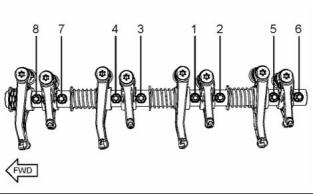
Illustration 13
Tightening sequence
Tighten the fasteners in the sequence that is in
illustration 13. Tighten the fasteners to the following
torque. ............................................. 35 N·m (26 lb ft)
i04351269
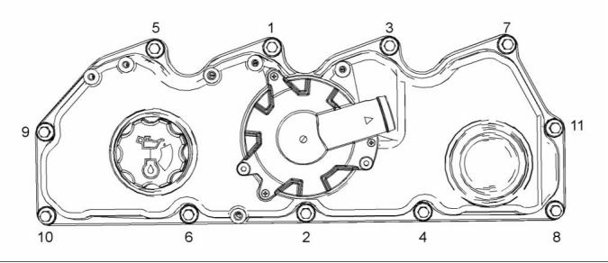
Valve Mechanism Cover
g02161123
Illustration 14
Typical example
This document is printed from SPI². Not for RESALE
![]()
![]()
![]()
KENR9123-01
11
Specifications Section
Tighten the fasteners for the valve mechanism cover
in the sequence that is shown in illustration 14 to the
following torque. .............................. 22 N·m (16 lb ft)
i04458277
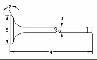
Cylinder Head Valves
g01335204
Illustration 16
(2) Valve face angle
Inlet ................................................... 30 degrees
Exhaust ............................................. 45 degrees
(3) Valve stem diameter
Inlet .. 5.942 to 5.957 mm (0.2339 to 0.2345 inch)
Exhaust ................................. 5.927 to 5.942 mm
(0.2333 to 0.2339 inch)
Clearance
Maximum clearance of the inlet valve
stem ................................ 0.05 mm (0.0020 inch)
The service limit for the inlet valve
stem ................................ 0.08 mm (0.0031 inch)
g01335203
Illustration 15
Typical example
Clearance
When the valve springs (1) are replaced the valve
springs must be replaced in pairs.
Maximum clearance of the exhaust valve
stem .............................. 0.065 mm (0.0026 inch)
The service limit for the exhaust valve
Table 1
stem ................................ 0.09 mm (0.0035 inch)
The load for the inlet valve The length of the inlet valve
(4) Length of valve
spring
spring
209 to 231 N (47 to 52 lb)
31.5 mm (1.2402 inch)
22.2 mm (0.87401 inch)
Inlet valve ..................... 107.925 to 108.375 mm
(4.2490 to 4.2667 inch)
Exhaust valve ............... 107.703 to 108.153 mm
389.5 to 430.5 N
(87.5 to 97 lb)
(4.2403 to 4.2580 inch)
Table 2
(5) Valve head
The load for the exhaust
valve spring
The length of the exhaust
valve spring
Diameter of inlet valve head .................... 35 mm
(1.3780 inch)
Diameter of exhaust valve head .............. 33 mm
(1.2992 inch)
161.5 to 178.5 N
(36.3 to 40.1 lb)
31.5 mm (1.2402 inch)
337.9 to 373.5 N
(76 to 84 lb)
21.5 mm (0.8465 inch)
This document is printed from SPI². Not for RESALE
![]()
![]()


![]()
12
KENR9123-01
Specifications Section
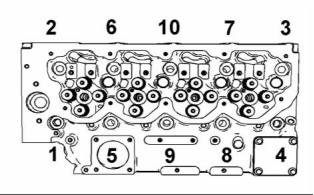
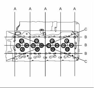
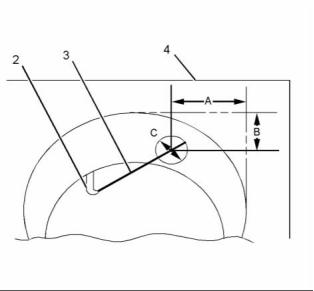
i04136793
Table 3
Cylinder Head
Maximum Permissible
Distortion
Dimension
Width (A)
0.03 mm (0.0018 inch)
0.05 mm (0.0019 inch)
0.05 mm (0.0019 inch)
Length (B)
Diagonal Line (C)
g01250785
Illustration 17
Typical example
Lubricate the threads and the underside of the head
bolts with clean engine oil.
Tighten the bolts in the sequence that is shown in
illustration 17 to the following torque. ...... 50 N·m
(37 lb ft)
Tighten the bolts again to the following
torque. .................................... 100 N·m (74 lb ft)
Tighten the head bolts to the additional
amount. ........................................... 225 degrees
Minimum thickness of cylinder head ......... 150.8 mm
(5.93700 inch)
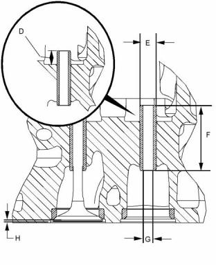
g02328933
Illustration 19
Typical example
(D) Valve guide height from the top of the valve guide
to the valve spring seat .......... 10.75 to 11.25 mm
(0.42323 to 0.44291 inch)
(E) Outside diameter of the valve
guides ................................ 11.029 to 11.040 mm
(0.43421 to 0.43464 inch)
(F) Length of the valve guides ... 43.75 to 44.25 mm
(1.72244 to 1.74212 inch)
(G) Internal diameter of the valve
guides ................................... 7.007 to 7.020 mm
(0.27587 to 0.27638 inch)
(H) Valve depths
Inlet .. 0.905 to 1.163 mm (0.0356 to 0.0458 inch)
The service limit for the depth of the inlet valve
........................................ 1.41 mm (0.0555 inch)
Exhaust ................................. 0.876 to 1.131 mm
(0.0345 to 0.0445 inch)
The service limit for the exhaust valve
depth ............................... 1.38 mm (0.0543 inch)
g01455374
Illustration 18
Note: The maximum distortion of the bottom face of
the cylinder head is given in table 3.
This document is printed from SPI². Not for RESALE
![]()
![]()
![]()

![]()
![]()
KENR9123-01
13
Specifications Section
(L) Seat surface finish ...................... Ra 0.8 microns
(M) Concentricity of valve seat to valve guide
parent bore Maximum Total Indicated Reading
(TIR) ............................. 0.08 mm (0.00315 inch)
i04303429
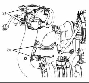
Turbocharger
(Series Turbochargers)
Note: For the correct procedure to install the
turbochargers, refer to Disassembly and Assembly,
“Turbocharger - Install”.
g02474819
Illustration 20
Typical example
(J) Diameter of the parent bore in the cylinder
head ................................... 11.000 to 11.022 mm
(0.43307 to 0.43394 inch)
(K) Seat angle
Inlet ............................................. 119.15 degrees
Exhaust ........................................ 89.15 degrees
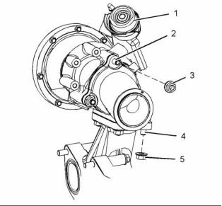
g02467657
Illustration 22
Typical example
(1) Actuator
The test pressure for the wastegate
actuator .................................. 100 kPa (14.5 psi)
The movement for the rod actuator ........... 1 mm
(0.0394 inch)
(2) Tighten the studs to the following torque. .. 11 N·m
(97 lb in)
(3) Tighten the nuts to the following torque. .. 24 N·m
(18 lb ft)
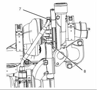
g02475018
Illustration 21
Typical example
This document is printed from SPI². Not for RESALE
![]()
![]()
![]()
![]()
14
KENR9123-01
Specifications Section
g02467764
g02467817
Illustration 23
Illustration 25
Typical example
Typical example
(4) Tighten the studs to the following
(9) Tighten the nut to the following torque. .. (22 lb ft)
torque. ...................................... 18 N·m (13 lb ft)
(10), (14), (15) Tighten the bolts to the following
torque. ...................................... 22 N·m (16 lb ft)
(5) Tighten the bolts to the following torque. .. 44 N·m
(32 lb ft)
(11), (12) Tighten the bolt to the following
torque. ...................................... 18 N·m (13 lb ft)
(6) Tighten the nuts to the following torque. .. 44 N·m
(32 lb ft)
(13) Tighten the bolt to the following torque. .. 40 N·m
(29 lb ft)
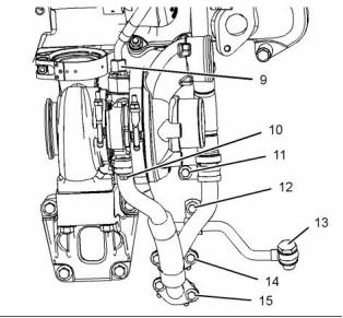
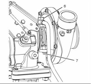
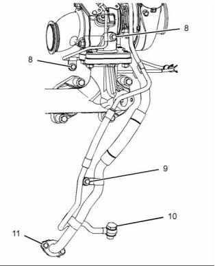
g02467778
Illustration 24
Typical example
g02469656
Illustration 26
(7) Tighten the bolt to the following torque. ... 22 N·m
(16 lb ft)
Typical example
(16) Tighten the clamps to the following
(8) Tighten the bolts to the following torque. ... 9 N·m
(80 lb in)
torque. .................................... 12 N·m (106 lb in)
This document is printed from SPI². Not for RESALE
![]()
![]()
![]()
![]()
![]()
KENR9123-01
15
Specifications Section
(17) Tighten the clamps to the following
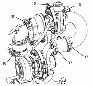
i04303430
torque. ........................................ 6 N·m (53 lb in)
Turbocharger
(Single Turbocharger)
g02469659
Illustration 27
Typical example
(18) Tighten the bolts to the following
torque. ...................................... 22 N·m (16 lb ft)
(19) Tighten the bolt to the following torque. .. 15 N·m
(11 lb ft)
g02469696
Illustration 29
Typical example
(1) Actuator
The test pressure for the wastegate
actuator .................................. 100 kPa (14.5 psi)
The movement for the rod actuator ........... 1 mm
(0.0394 inch)
(2) Tighten the studs to the following
torque. ...................................... 18 N·m (13 lb ft)
(3) Tighten the nuts to the following torque. .. 44 N·m
(32 lb ft)
(4) Tighten the studs to the following
torque. ...................................... 18 N·m (13 lb ft)
(5) Tighten the nuts to the following torque. .. 44 N·m
(32 lb ft)
g02469676
Illustration 28
Typical example
(20) Tighten the bolts to the following
torque. ...................................... 22 N·m (16 lb ft)
(21) Tighten the clamps to the following
torque. .................................... 12 N·m (106 lb in)
This document is printed from SPI². Not for RESALE
![]()
![]()
![]()
![]()
16
KENR9123-01
Specifications Section
(9) Tighten the bolts to the following torque. .. 18 N·m
(13 lb ft)
(10) Tighten the bolt to the following torque. .. 40 N·m
(30 lb ft)
(11) Tighten the bolts to the following
torque. ...................................... 22 N·m (16 lb ft)
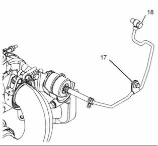
g02469717
Illustration 30
Typical example
(6) Tighten the bolt to the following torque. ... 22 N·m
(16 lb ft)
(7) Tighten the bolt to the following torque. ..... 9 N·m
(80 lb in)
g02469836
Illustration 32
Typical example
(12) Tighten the bolt to the following torque. .. 22 N·m
(16 lb ft)
(13) Tighten the bolt to the following torque. .. 15 N·m
(11 lb ft)
g02469740
Illustration 31
Typical example
g02469857
Illustration 33
Typical example
(8) Tighten the bolt to the following torque. ... 22 N·m
(16 lb ft)
This document is printed from SPI². Not for RESALE
![]()
![]()
![]()
![]()
![]()
KENR9123-01
17
Specifications Section
(14) Tighten the clamps to the following
torque. .................................... 12 N·m (106 lb in)
i04138516
Exhaust Gas Valve (NRS)
g02337116
Illustration 35
Typical example
(2) Tighten the stud to the following torque. .. 11 N·m
(97 lb in)
(3) Tighten the plug to the following torque. .. 35 N·m
(26 lb ft)
g02337096
Illustration 34
Typical example
(1) Tighten the bolts to the following torque. .. 22 N·m
(16 lb ft)
g02337117
Illustration 36
Typical example
(4) Tighten the bolts to the following torque. ... 9 N·m
(80 lb in)
(5) Tighten the plug to the following torque. .. 9.5 N·m
(84 lb in)
This document is printed from SPI². Not for RESALE
![]()
![]()
![]()
![]()
18
KENR9123-01
Specifications Section
i04448752
Exhaust Sensor and Lines
(NRS)
Table 4
Required Tools
Part Number Part Description
Tool
QTY
Bostik Pure Nickel
Anti-Seize Compound
A
-
1
g02337118
Illustration 37
Typical example
(6) Tighten the nut to the following torque. .... 18 N·m
(13 lb ft)
(7) Tighten the bolts to the following torque. .. 18 N·m
(13 lb ft)
g02148954
Illustration 39
Typical example
Note: Apply Tooling (A) to the sensors before the
sensors are installed.
(1) Tighten the sensors to the following
torque. ...................................... 45 N·m (33 lb ft)
Tighten the harness for the sensors (not shown) to
the following torque. .................... 1.2 N·m (10.6 lb in)
g02337119
Illustration 38
Typical example
(8) Tighten the bolts to the following torque. ... 9 N·m
(80 lb in)
This document is printed from SPI². Not for RESALE
![]()
![]()
![]()

![]()
KENR9123-01
19
Specifications Section
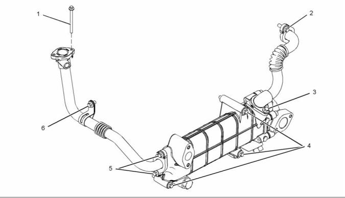
i04138514
Exhaust Cooler (NRS)
Note: When the pipes for the exhaust cooler are
removed or installed, care must be taken so that the
pipes are not bent or the pipes are not damaged.
g02337136
Illustration 40
Typical example
(1) Tighten the bolts to the following torque. ... 9 N·m
(80 lb in)
(2) Tighten the bolts to the following torque. .. 22 N·m
(16 lb ft)
(3) Tighten the bolts to the following torque. .. 22 N·m
(16 lb ft)
(4) Tighten the bolts to the following torque. .. 22 N·m
(16 lb ft)
(5) Tighten the bolts to the following torque. .. 22 N·m
(16 lb ft)
(6) Tighten the bolt to the following torque. ... 22 N·m
(16 lb ft)
This document is printed from SPI². Not for RESALE
![]()
![]()
20
KENR9123-01
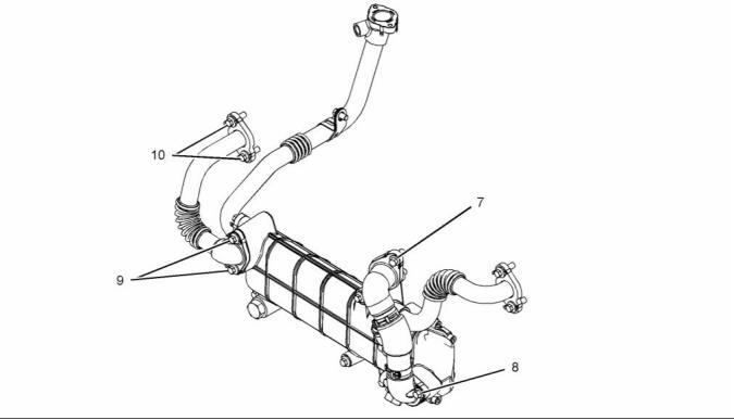
Specifications Section
g02337137
Illustration 41
Typical example
(7), (8) Tighten the bolts to the following
torque. ...................................... 22 N·m (16 lb ft)
(9) Tighten the bolts to the following torque. .. 22 N·m
(16 lb ft)
(10) Tighten the bolts to the following
torque. ...................................... 22 N·m (16 lb ft)
This document is printed from SPI². Not for RESALE
![]()
![]()
KENR9123-01
21
Specifications Section
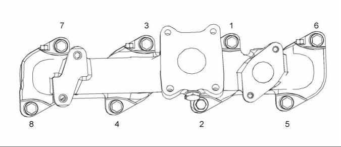
i03914512
Exhaust Manifold
g02150456
Illustration 42
Typical example
Tighten the exhaust manifold bolts in the sequence
that is shown in illustration 42 to the following
torque. ............................................. 44 N·m (32 lb ft)
This document is printed from SPI². Not for RESALE
![]()
![]()
22
KENR9123-01
Specifications Section
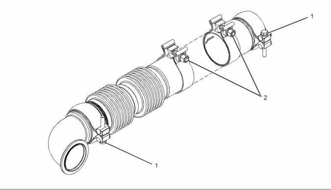
i03936932
Flexible Exhaust Pipe
g02155429
Illustration 43
Typical example
(1) Tighten the clamp to the following
torque. ...................................... 35 N·m (26 lb ft)
(2) Tighten the clamp to the following
torque. ...................................... 55 N·m (41 lb ft)
Refer to Disassembly and Assembly for the correct
procedure to install the flexible exhaust pipe.
i04229372
Diesel Particulate Filter
Note: To remove and install the Diesel Particulate
Filter (DPF), refer to Disassembly and Assembly for
the correct procedures.
This document is printed from SPI². Not for RESALE
![]()
![]()
KENR9123-01
23
Specifications Section
Maximum permissible end play of a worn
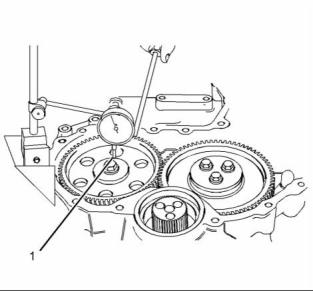
camshaft ............................... 0.62 mm (0.0244 inch)
g02405938
Illustration 44
Typical example
g02150828
Illustration 46
(1) Tighten the nuts on clamps to the following
torque. ...................................... 17 N·m (13 lb ft)
Typical example
(2) Bolt
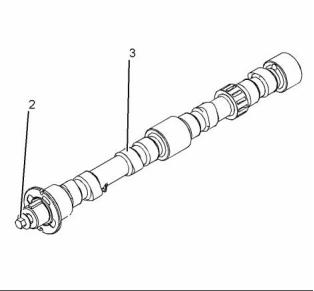
i04156670
, Torque for the 8.8 graded bolt .. 95 N·m (70 lb ft)
Torque for the 10.9 graded bolt ............. 120 N·m
(89 lb ft)
Camshaft
(3) The diameters of the camshaft journals are given
in the following tables.
Table 5
Camshaft Journals
from the Front End
of the Engine
Standard Diameter
1
Front
50.711 to 50.737 mm
(1.9965 to 1.9975 inch)
50.457 to 50.483 mm
(1.9865 to 1.9875 inch)
2
3
Rear
49.949 to 49.975 mm
(1.9665 to 1.9675 inch)
Maximum wear on the camshaft journals ... 0.05 mm
(0.0021 inch)
Check the camshaft lobes for visible damage. If a
new camshaft is installed, you must install new lifters.
g01927854
Illustration 45
Checking the end play of the camshaft
(1) End play of a camshaft ......... 0.106 to 0.558 mm
(0.00417 to 0.02197 inch)
This document is printed from SPI². Not for RESALE
![]()
![]()
![]()
![]()

24
KENR9123-01
Specifications Section
(1) The diameter of the installed camshaft
bearing .............................. 50.787 to 50.848 mm
(1.9995 to 2.0019 inch)
i03914549
Engine Oil Filter Base
g02474757
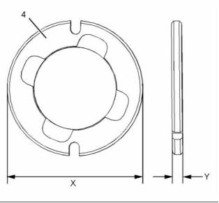
Illustration 47
Typical example
(4) Camshaft thrust washer
Outer diameter (X) ............ 72.949 to 73.000 mm
(2.872 to 2.874 inch)
Thickness (Y) ........................ 5.486 to 5.537 mm
(0.21598 to 0.21799 inch)
i03916857
g02150462
Illustration 49
Camshaft Bearings
Typical example
(1) Setscrew
Torque for the setscrews .......... 22 N·m (16 lb ft)
(2) Dust cap
(3) Oil sampling valve
Torque for the Oil sampling valve ............ 12 N·m
(106 lb in)
Torque for the plug (if equipped) .. 12 N·m (106 lb in)
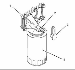
(4) Engine oil filter
Torque for the engine oil filter .. 12 N·m (106 lb in)
g02150875
Illustration 48
Typical example
This document is printed from SPI². Not for RESALE
![]()
![]()
![]()
![]()
KENR9123-01
25
Specifications Section
i04406752
i04346632
Engine Oil Cooler
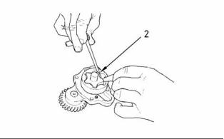
Engine Oil Pump
Type ............................. Gear-driven differential rotor
Number of lobes
Inner rotor ......................................................... 6
Outer rotor ........................................................ 7
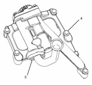
g02600976
g00938064
Illustration 50
Illustration 52
Typical example
Typical example
Tighten the setscrews in the sequence that is in
illustration 50 to the following torque. ............ 10 N·m
(89 lb in)
(1) Clearance of the outer rotor to the
body ...................................... 0.050 to 0.330 mm
(0.0020 to 0.0130 inch)
g00938061
Illustration 53
Checking the clearance
(2) Service limit of inner rotor to outer
rotor ...................................... 0.080 to 0.250 mm
(0.0031 to 0.0098 inch)
g02600977
Illustration 51
Typical example
Tighten the setscrews in the sequence that is in
illustration 51 to the following torque. ............ 26 N·m
(19 lb ft)
This document is printed from SPI². Not for RESALE
![]()
![]()
![]()
![]()
![]()
26
KENR9123-01
Specifications Section
i03994212
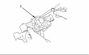
Engine Oil Pressure
The minimum oil pressure at a maximum engine
speed of 2200 rpm and at normal operating
temperature is the following value. .. 280 kPa (40 psi)
i04315734
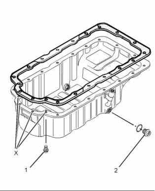
Engine Oil Pan
g00938799
Illustration 54
Checking the end play
(3) End play of rotor assembly
Inner rotor ............................. 0.050 to 0.180 mm
(0.0020 to 0.0071 inch)
Table 6
Required Tools
Outer rotor ............................ 0.050 to 0.180 mm
(0.0020 to 0.0071 inch)
Tool
Part Number
Part Description
Qty
A
-
Loctite 5900
1
Front sealant
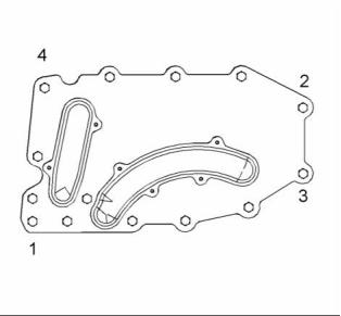
g02501636
Illustration 55
Typical example
(4) Tighten the bolts to the following torque. .. 44 N·m
(32 lb ft)
g01254690
Illustration 56
Applying sealant
(5) Tighten the bolts to the following torque. .. 22 N·m
(16 lb ft)
Apply Tooling (A) to the cylinder block and to the
timing case.
Note: Apply a sealant bead of 3.5 mm (0.1378 inch)
that is shown in illustration 56.
Rear sealant
Note: Install the rear oil seal before sealant is applied
to the bridge.
This document is printed from SPI². Not for RESALE
![]()
![]()
![]()

![]()
KENR9123-01
27
Specifications Section
Tighten the remaining bolts to the following
torque. ............................................. 22 N·m (16 lb ft)
(2) Drain plug
Tighten the drain plug for the engine oil pan to
the following torque. ................. 34 N·m (25 lb ft)
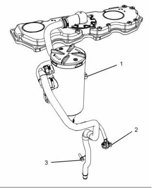
i03969629
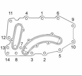
Crankcase Breather
g01254887
Illustration 57
Applying sealant
ApplyTooling (A) to the bridge. The sealant must not
protrude more than 5 mm (0.1969 inch) above the
bridge.
g02162137
Illustration 59
Typical example
(1), (2), (3) Tighten the setscrews to the following
torque. ...................................... 22 N·m (16 lb ft)
g01255016
Illustration 58
Typical example
(1) Tighten the four front bolts in position (X) to the
following torque. ....................... 22 N·m (16 lb ft)
This document is printed from SPI². Not for RESALE
![]()
![]()
![]()
![]()
28
KENR9123-01
Specifications Section
i03916250
Opening temperature ........................ 80° to 84°C
(151° to 176°F)
Water Temperature Regulator
and Housing
Maximum open length of 11 mm (0.43307 inch) is
achieved at the following temperature. ...... 94° C
(201° F)
i03916132
Water Pump
g02150761
Illustration 60
Typical example
(3) Water temperature regulator housing
(1) Torque for the vent plug ....... 22 N·m (16.22 lb ft)
g02150757
Illustration 62
(2) Torque for the bolts that fasten the housing to the
cylinder head ............................ 22 N·m (16 lb ft)
Tightening sequence
Tighten the setscrews in the numerical sequence
that is shown in illustration 62 to the following
torque. ............................................. 22 N·m (16 lb ft)
g02150762
Illustration 61
Typical example
(4) Water temperature regulator
This document is printed from SPI². Not for RESALE
![]()
![]()
![]()
![]()
KENR9123-01
29
Specifications Section
i03917011
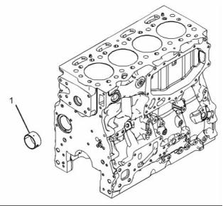
Bore in the cylinder block for the main
bearings ............................ 88.246 to 88.272 mm
(3.4742 to 3.4753 inch)
Cylinder Block
(5) Main bearing cap bolts
Use the following procedure in order to install the
main bearing cap bolts:
1. Apply clean engine oil to the threads of the main
bearing cap bolts.
2. Put the main bearing caps in the correct position
that is indicated by a number on the top of the
main bearing cap. Install the main bearing caps
with the locating tabs in correct alignment with the
recess in the cylinder block.
3. Evenly tighten the main bearing cap bolts.
Torque for the main bearing cap bolts. ...... 80 N·m
(59 lb ft)
4. After torquing the bolts for the main bearing caps,
the bolts must be rotated for an additional 90
degrees.
Note: Ensure that the crankshaft can rotate freely.
g02150944
Illustration 63
Typical example
i04129189
(1) Cylinder block
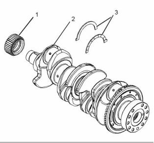
Crankshaft
(2) Cylinder bore ................ 105.000 to 105.025 mm
(4.1338 to 4.1348 inch)
The maximum permissible wear for the cylinder
bore ....................................... 0.15 mm (0.0059 inch)
(3) Camshaft bearings
Diameter of the bushing in the cylinder
block for the number 1 camshaft
bearing .............................. 55.563 to 55.593 mm
(2.1875 to 2.1887 inch)
Diameter of the bore in the cylinder
block for the number 2 camshaft
journal ............................... 50.546 to 50.597 mm
(1.9900 to 1.9920 inch)
Diameter of the bore in the cylinder
block for the number 3 camshaft
journal ............................... 50.292 to 50.343 mm
(1.9800 to 1.9820 inch)
Diameter of the bore in the cylinder
block for the number 4 camshaft
journal ............................... 50.038 to 50.089 mm
(1.9700 to 1.9720 inch)
g02155393
Illustration 64
Typical example
(4) Main bearings
(1) Crankshaft gear
(2) Crankshaft
(3) Crankshaft thrust washers
This document is printed from SPI². Not for RESALE
![]()
![]()
![]()
30
KENR9123-01
Specifications Section
Maximum permissible temperature of the gear for
installation on the crankshaft ........... 180 °C (356 °F)
Maximum permissible temperature of the drive gear
for the balancer (if equipped) for installation on the
crankshaft ........................................ 180 °C (356 °F)
Note: Refer to Disassembly and Assembly for the
correct procedure to remove and install the drive
gear for the balancer.
The end play of a new crankshaft ..... 0.1 to 0.41 mm
(0.00394 to 0.01614 inch)
Standard thickness of thrust
washer .. 2.69 to 2.75 mm (0.10591 to 0.10827 inch)
Oversize thickness of thrust
washer ... 2.89 to 2.95 mm (0.11378 to 0.11614 inch)
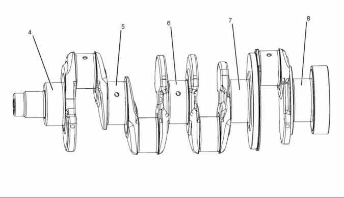
g02155394
Illustration 65
Typical example
(4) Journal 1
(5) Journal 2
(6) Journal 3
(7) Journal 4
(8) Journal 5
Refer to table 7 for the run out of the crankshaft
journals.
Table 7
Journal
(1)
Run out of the Journals
Mounting
(2)
0.08 mm (0.0031 inch)
0.15 mm (0.0059 inch)
0.08 mm (0.0031 inch)
Mounting
(3)
(4)
(5)
This document is printed from SPI². Not for RESALE
![]()
![]()

KENR9123-01
31
Specifications Section
Inspect the crankshaft for wear or for damage. For
more information regarding the servicing of the
crankshaft, contact the Global Technical Support
Center.
Refer to Specifications, “Connecting Rod Bearing
Journal” for more information on the connecting rod
bearing journals and connecting rod bearings.
Refer to Specifications, “Main Bearing Journal” for
information on the main bearing journals and for
information on the main bearings.
i02934550
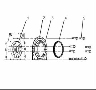
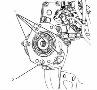
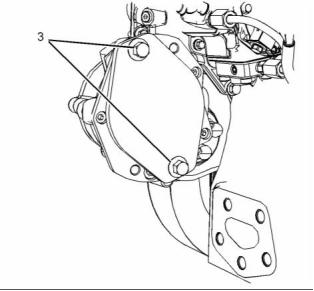
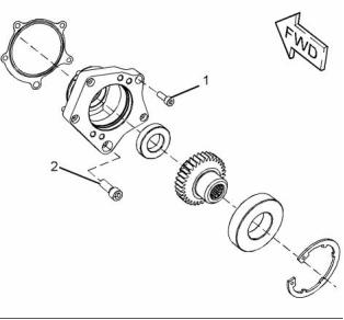
Crankshaft Seals
g00915076
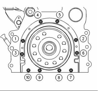
Illustration 67
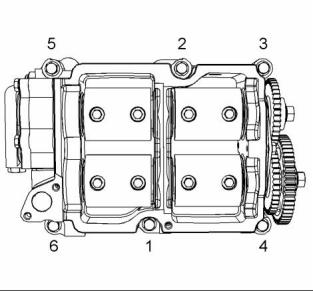
(5) Tighten bolts 1, 2, 3, 4, 5, 6, 7, and 10 in the
sequence that is shown in Illustration 67 to the
following torque. ....................... 22 N·m (16 lb ft)
Remove the alignment tool.
Tighten bolts 8 and 9 in the sequence that is shown
in Illustration 67 to the following torque. ........ 22 N·m
(16 lb ft)
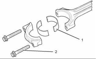
i03996317
Connecting Rod Bearing
Journal
g01455434
Illustration 66
Typical example
The original size of the connecting rod bearing journal
on the crankshaft ........................ 67.99 to 68.01 mm
(2.67677 to 2.67755 inch)
(1) Crankshaft
(2) Crankshaft seal
(3) Plastic sleeve
(4) Alignment tool
Maximum permissible wear of a bearing journal
on the crankshaft when a new connecting rod is
installed ................................. 0.04 mm (0.0016 inch)
Width of the connecting rod bearing journals on the
crankshaft ............................... 40.305 to 40.455 mm
(1.58681 to 1.59271 inch)
Surface finish of connecting rod bearing
journals ........................................... Ra 0.25 microns
This document is printed from SPI². Not for RESALE
![]()
![]()
![]()
32
KENR9123-01
Specifications Section
i03996318
i04285130
Main Bearing Journal
Connecting Rod
The original size of the main bearing
journal ..................................... 83.980 to 84.000 mm
(3.30629 to 3.30708 inch)
Maximum permissible wear of the main bearing
journals ............................... 0.040 mm (0.0016 inch)
Surface finish of bearing journals and crank pins
........................................................ Ra 0.25 microns
Width of new main bearing journal where the thrust
washer is installed .................. 39.765 to 39.835 mm
(1.56555 to 1.56830 inch)
g01254512
Width of new main bearing journal where the thrust
washer is not installed ................ 39.19 to 39.39 mm
(1.54291 to 1.55078 inch)
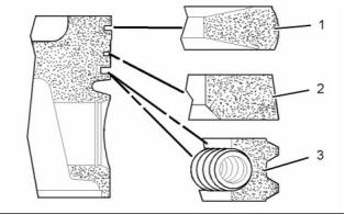
Illustration 68
Typical example
(1) The bearing shell for the connecting rod
The shell for the main bearings
For the correct procedure to install the bearing
shell for the connecting rod, refer to Disassembly
and Assembly, “Pistons and Connecting Rods -
Assemble”.
The shells for the main bearings are available
for remachined journals which have the following
oversize dimensions.
Table 8
Oversize bearing shell ...... 0.25 mm (0.010 inch)
Oversize bearing shell ...... 0.50 mm (0.020 inch)
Oversize bearing shell ...... 0.76 mm (0.030 inch)
Thickness of Connecting
1.995 to 2.002 mm
Rod Bearing at the
(0.07854 to 0.07882 inch)
Center
Thickness at center of the shells of oversize bearing
shell 0.25 mm (0.010 inch) ......... 2.226 to 2.232 mm
(0.08764 to 0.08787 inch)
0.031 to 0.038 mm
Bearing Clearance
(0.00122 to 0.00150 inch)
Table 9
Thickness at center of the shells of oversize bearing
shell 0.50 mm (0.020 inch) ......... 2.353 to 2.359 mm
(0.09264 to 0.09287 inch)
Oversize Connecting Rod Bearing
0.25 mm (0.010 inch)
0.51 mm (0.020 inch)
0.76 mm (0.030 inch)
Thickness at center of the shells of oversize bearing
shell 0.76 mm (0.030 inch) ......... 2.480 to 2.486 mm
(0.09764 to 0.09787 inch)
Width of the main bearing shells .. 26.32 to 26.58 mm
(1.03622 to 1.04645 inch)
Clearance between the bearing shell and the main
bearing journals .......................... 0.036 to 0.094 mm
(0.00142 to 0.00370 inch)
This document is printed from SPI². Not for RESALE
![]()
![]()


KENR9123-01
33
Specifications Section
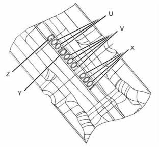
g01950657
Illustration 69
Typical example
(U) Day code
(V) Code for the connecting rod
(X) Code for the Connecting rod cap
(Y) Year code
(Z) Code for the grade of connecting rod
g01254518
Illustration 70
Note: The day code is from the first day in the
year. For example, “001” will be the first day of the
appropriate year.
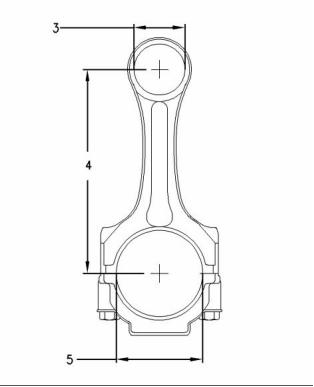
Typical example
(3) Diameter of the finished bore for the piston
pin ..................................... 39.738 to 39.723 mm
(1.5645 to 1.5639 inch)
The mating surfaces of the connecting rod are
produced by hydraulically fracturing the forged
connecting rod. Ensure that the correct cap for
the connecting rod is installed with the correct
connecting rod. Ensure that the serial numbers for
both components match.
(4) Distance between the parent bores
...... 219.05 to 219.1 mm (8.6240 to 8.6260 inch)
(5) Diameter for the finished bore for the connecting
rod bearing ....................... 72.045 to 72.058 mm
(2.83641 to 2.83692 inch)
(2) Torque of the setscrews for the connecting rod
.................................................. 40 N·m (30 lb ft)
The connecting rod is color coded. The color code
is a reference for the length of the connecting rod.
Refer to table 10 for the length of connecting rod.
Tighten the setscrews for the connecting rod for
an additional 120 degrees. The setscrews for the
connecting rod (2) must be replaced after this
procedure.
Table 10
Specifications for the Connecting Rod
Note: Always tighten the connecting rod cap to the
connecting rod, when the assembly is out of the
engine. Tighten the assembly to the following torque
20 N·m (14 lb ft).
Grade
Letter
Length Of The
Connecting Rod
Color Code
163.081 to 163.114 mm
(6.42050 to 6.42180
inch)
B
Blue
This document is printed from SPI². Not for RESALE
![]()
![]()
![]()

34
KENR9123-01
Specifications Section
i04041471
Width of oil control ring ............. 2.97 to 2.99 mm
(0.1169 to 0.1177 inch)
Piston and Rings
The clearance between a new oil control ring and
the groove in a new piston ........ 0.03 to 0.07 mm
(0.0011 to 0.0027 inch)
Ring gap ................................... 0.30 to 0.55 mm
(0.0118 to 0.0216 inch)
Note: When you install a new oil control ring, make
sure that the word “TOP” is facing the top of the
piston. New oil control rings have a red identification
mark. The identification mark must be on the left
of the ring end gap when the top piston ring is
installed on an upright piston. The oil control ring is
a two-piece ring that is spring loaded. A pin is used
in order to hold both ends of the spring of the oil
control ring in position. The ends of the spring of the
oil control ring must be installed opposite the end gap
of the oil control ring.
Note: Ensure that the ring end gaps of the piston
rings are spaced 120 degrees from each other.
g01155119
Illustration 71
Typical example
Piston
(1) Top compression ring
The shape of the top compression
ring ....................................................... Keystone
Note: An arrow which is marked on the piston crown
must be toward the front of the engine.
Ring gap ................................... 0.30 to 0.40 mm
(0.01181 to 0.01575 inch)
Piston height above cylinder block .. 0.55 to 0.20 mm
(0.02165 to 0.00787 inch)
Note: When you install a new top compression ring,
make sure that the word “TOP” is facing the top
of the piston. New top piston rings have a black
identification mark. The identification mark must be
on the left of the ring end gap when the top piston
ring is installed on an upright piston.
Width of top groove in the piston ................. Tapered
Width of second groove in new
piston ........ 2.56 to 2.58 mm (0.1008 to 0.1016 inch)
Width of third groove in new piston .. 3.02 to 3.04 mm
(0.1189 to 0.1197 inch)
(2) Intermediate compression ring
Piston pin
The shape of the intermediate compression
ring ....................................... Internal bevel in the
bottom edge with a tapered face
Diameter of a new piston
pin ..................................... 39.694 to 39.700 mm
(1.5628 to 1.5630 inch)
Width of intermediate compression
ring .... 2.47 to 2.495 mm (0.0972 to 0.0982 inch)
The clearance between a new intermediate
compression ring and the piston groove in a new
piston ..................................... 0.065 to 0.110 mm
(0.00256 to 0.00433 inch)
Ring gap ................................... 0.65 to 0.85 mm
(0.0256 to 0.0335 inch)
Note: When you install a new intermediate
compression ring, make sure that the word “TOP” is
facing the top of the piston. New intermediate rings
have a blue identification mark. The identification
mark must be on the left of the ring end gap when the
top piston ring is installed on an upright piston.
(3) The oil control ring
This document is printed from SPI². Not for RESALE
![]()
![]()
KENR9123-01
35
Specifications Section
i02696381
2. Dimension (A) is 50.75 mm (1.9980 inch)
and dimension (B) is 9.35 mm (0.3681 inch).
Dimension (A) and dimension (B) are tangential
to the cylinder bore (4).
Piston Cooling Jet
3. The position of the rod (3) must be within
dimension (C). Dimension (C) is 14 mm
(0.5512 inch).
Note: Ensure that the rod (3) can not damage the
piston cooling jet when the alignment is checked. The
piston cooling jets can not be adjusted. If a piston
cooling jet is not in alignment the piston cooling jet
must be replaced.
i04313812
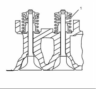
Balancer Group
g01352576
Illustration 72
(1) Installed piston cooling jets
The valve must move freely. Tighten the bolt to the
following torque. .................................. 9 N·m (7 lb ft)
Piston Cooling Jet Alignment
g02150753
Illustration 74
Typical example
Tighten the bolts in the sequence that is shown in
illustration 74 to the following torque. ............ 54 N·m
(40 lb ft)
g01352578
Illustration 73
Backlash values
(2) Piston cooling jet
(3) Rod
(4) Cylinder block
Backlash between crankshaft ring gear and the
balancer intermediate gear ... 0.020 to 0.240 mm
(0.0008 to 0.009 inch)
Use the following procedure in order to check the
alignment of the piston cooling jet.
Backlash between the balancer shaft
gears ..................................... 0.020 to 0.160 mm
(0.0008 to 0.0063 inch)
1. Insert rod (3) into the end of the piston cooling
jet (2). Rod (3) has a diameter of 1.70 mm
(0.067 inch). Rod (3) must protrude out of the top
of the cylinder block.
This document is printed from SPI². Not for RESALE
![]()
![]()
![]()
![]()
36
KENR9123-01
Specifications Section
i03907005
(3) Tighten bolts to the following torque. ....... 44 N·m
(33 lb ft)
Accessory Drive
(SAE “B”)
i03907004
Accessory Drive
g02148374
Illustration 75
Typical example
g02148372
Illustration 77
(1) Tighten allen head screws to the following
torque. ...................................... 22 N·m (16 lb ft)
Typical example
(1) Tighten the allen head screws to the following
torque. ...................................... 22 N·m (16 lb ft)
(2) Tighten the allen head screw to the following
torque. ...................................... 78 N·m (58 lb ft)
(2) Tighten the allen head screws to the following
torque. ...................................... 78 N·m (58 lb ft)
g02148375
Illustration 76
Typical example
This document is printed from SPI². Not for RESALE
![]()
![]()
![]()
![]()
KENR9123-01
37
Specifications Section
i03917090
(2) Tighten the bolts that fasten the water pump to the
front housing to the following torque. ....... 22 N·m
(16 lb ft)
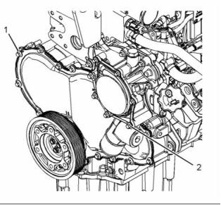
Front Housing and Covers
Note: Refer to Specifications, “Water Pump” for the
correct bolt tightening sequence for the water pump.
i04351939
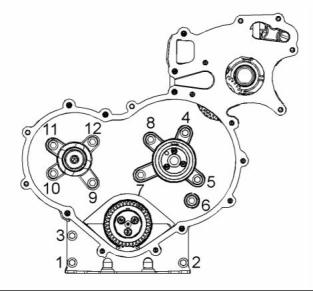
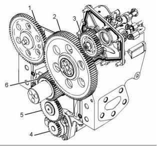
Gear Group (Front)
g01860874
Illustration 78
Typical example
Tighten the setscrew to the sequence that is shown
in illustration 78 to the following torque. ......... 28 N·m
(20 lb ft)
g01857156
Illustration 80
Gear train
(1) Camshaft gear
Torque for the 8.8 graded bolt for the camshaft
gear .......................................... 95 N·m (70 lb ft)
Torque for the 10.9 graded bolt for the camshaft
gear ........................................ 120 N·m (89 lb ft)
Number of teeth .............................................. 72
(2) Idler gear and hub
Torque for the bolts for the idler gear ....... 44 N·m
(33 lb ft)
Width of light duty idler gear and bearing
assembly .............................. 19.95 to 20.05 mm
(0.78543 to 0.78937 inch)
Width of medium duty and heavy duty idler gear
and bearing assembly .......... 25.45 to 25.55 mm
(1.00197 to 1.00590 inch)
g02150954
Illustration 79
Typical example
Inside diameter of light duty idler gear
bearings ............................ 60.022 to 60.052 mm
(2.36307 to 2.36425 inch)
(1) Tighten the bolts that fasten the front cover to the
front housing to the following torque. ....... 22 N·m
(16 lb ft)
This document is printed from SPI². Not for RESALE
![]()
![]()
![]()
![]()
38
KENR9123-01
Specifications Section
Inside diameter of medium duty and heavy duty
idler gear bearings ................ 56.00 to 56.03 mm
(2.20472 to 2.20590 inch)
Backlash between the power take-off
drive (if equipped) and the idler gear
(2) ..... 0.05 to 0.250 mm (0.0020 to 0.0098 inch)
Outside diameter of light duty idler gear
hub ........................................ 59.95 to 59.97 mm
(2.36023 to 2.36102 inch)
(5) Oil pump idler gear
Inside diameter of oil pump idler gear
bearing .............................. 16.012 to 16.038 mm
(0.6304 to 0.6314 inch)
Outside diameter of medium duty and heavy duty
idler gear hub ........................ 55.95 to 55.97 mm
(2.20275 to 2.20354 inch)
Outside diameter of oil pump idler gear
shaft .................................. 15.966 to 15.984 mm
(0.6286 to 0.6293 inch)
Clearance of light duty idler gear bearing on
hub ........................................ 0.052 to 0.102 mm
(0.00205 to 0.00402 inch)
Clearance of oil pump idler gear bearing on
shaft ...................................... 0.028 to 0.072 mm
(0.0011 to 0.0028 inch)
Clearance of medium duty and heavy duty idler
gear bearing on hub ................. 0.03 to 0.08 mm
(0.00118 to 0.00315 inch)
End play of the oil pump idler
gear ...................................... 0.050 to 0.275 mm
(0.0019 to 0.0108 inch)
The end play of the light duty idler
gear .......................................... 0.05 to 0.25 mm
(0.00197 to 0.00984 inch)
End play of the oil pump drive
gear ...................................... 0.005 to 0.090 mm
(0.00020 to 0.00354 inch)
The end play of the medium duty and heavy duty
idler gear ................................... 0.05 to 0.15 mm
(0.00197 to 0.00591 inch)
(6) Crankshaft gear
Number of teeth .............................................. 97
Bore diameter of crankshaft gear
........ 51.00 to 51.03 mm (2.0079 to 2.0091 inch)
(3) Fuel injection pump drive gear
Outside diameter of crankshaft
hub .................................... 51.021 to 51.002 mm
(2.0087 to 2.0079 inch)
Torque for the nut ..................... 64 N·m (47 lb ft)
Number of teeth .............................................. 36
Clearance of gear on
crankshaft ......................... −0.021 to +0.028 mm
(4) Oil pump gear
(−0.00083 to 0.00110 inch)
The number of teeth on the oil pump gear ..... 21
Number of teeth .............................................. 36
Backlash values
Backlash between the oil pump idler gear (5) and
the oil pump drive gear (4) ........ 0.05 to 0.15 mm
(0.0020 to 0.0059 inch)
Backlash between the oil pump idler gear (5) and
the crankshaft gear (6) ......... 0.025 to 0.160 mm
(0.00098 to 0.00630 inch)
Backlash between the idler gear (2) and the
crankshaft gear (6) ................... 0.05 to 0.15 mm
(0.0020 to 0.0059 inch)
Backlash between the camshaft gear (1) and the
idler gear (2) ............................. 0.05 to 0.15 mm
(0.0020 to 0.0059 inch)
Backlash between the fuel injection pump gear
(3) and the idler gear (2) ........... 0.05 to 0.15 mm
(0.0020 to 0.0059 inch)
Backlash between the water pump gear (not
shown) and the fuel injection pump gear
(3) ....... 0.05 to 0.15 mm (0.0020 to 0.0059 inch)
This document is printed from SPI². Not for RESALE
![]()
KENR9123-01
39
Specifications Section
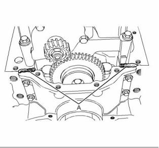
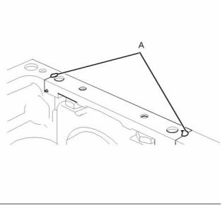
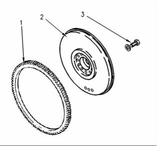
i03520340
Flywheel
g00584712
g01254486
Illustration 81
Illustration 82
Typical example
Typical example
(1) Flywheel ring gear
Setscrew
Heat the flywheel ring gear to the following
temperature. .............................. 250 °C (480 °F)
(1) Tighten the setscrew to the following
torque. ................................ 75 N·m (55 lb ft)
Note: Do not use an oxyacetylene torch to heat the
flywheel ring gear.
Setscrew
(2) Tighten the setscrew to the following
torque. ................................ 63 N·m (46 lb ft)
(2) Flywheel
(3) Bolt
Note: If 12.9 setscrews are installed, apply Tooling
(A) to the setscrews. Tighten the 12.9 setscrews to a
torque of 70 N·m (52 lb ft).
Tighten the flywheel bolts to the following
torque. .................................. 140 N·m (103 lb ft)
i04315754
Flywheel Housing
Table 11
Required Tools
Tool
Part Number
Part Description
Qty
A
-
Loctite 575
1
This document is printed from SPI². Not for RESALE
![]()
![]()

![]()
40
KENR9123-01
Specifications Section
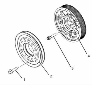
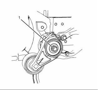
i03934631
i04083729
Crankshaft Pulley
Belt Tensioner
g02155003
g02291813
Illustration 83
Illustration 84
Typical example
Typical example
(1) Tighten the bolts to the following torque. .. 78 N·m
(58 lb ft)
(1) Tighten the bolt to the following torque. ... 45 N·m
(33 lb ft)
(3) Tighten the bolts to the following
torque. ................................... 22.5 N·m (17 lb ft)
Note: To install the belt tensioner, refer to
Disassembly and Assembly, “Belt Tensioner -
Remove and Install” for the correct procedure.
Note: Tighten the bolts (3) must be tightened through
an angle of 120 degrees.
(2) Auxiliary pulley
(4) Crankshaft pulley
This document is printed from SPI². Not for RESALE
![]()
![]()
![]()
KENR9123-01
41
Specifications Section
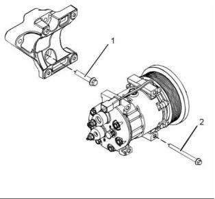
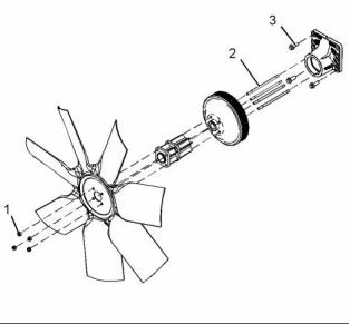
i03629003
i04089710
Refrigerant Compressor
Fan Drive
g01946810
g02297293
Illustration 85
Illustration 86
Typical example
Typical example
(1) Tighten the bolts to the following torque. .. 44 N·m
(32 lb ft)
(1) Tighten the locking nuts to the following
torque. ...................................... 22 N·m (16 lb ft)
(2) Tighten the bolts to the following torque. .. 22 N·m
(16 lb ft)
(2) Tighten the studs (if equipped) to the following
torque. ...................................... 11 N·m (97 lb in)
(3) Tighten the bolts to the following torque. .. 44 N·m
(32 lb ft)
i03520381
Engine Lifting Bracket
All engines are equipped engine lifting brackets.
Some lifting brackets require two bolts and some
lifting brackets may require four bolts.
Tighten the bolts on the engine lifting brackets to
the following torque. ................. 44 N·m (32 lb ft)
This document is printed from SPI². Not for RESALE
![]()
![]()
![]()
42
KENR9123-01
Specifications Section
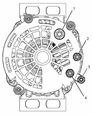
i03917270
Output
Alternator
The outputs of the alternators ........... 55 Amp, 80
Amp, 100 Amp, 120 Amp or 150 Amp
Alternator Bracket
The 12 V and 24 V Type 1
Alternators
g02151927
Illustration 88
Typical example
(1) Tighten the setscrews that secure the alternator
to the bracket to the following torque. ...... 50 N·m
(37 lb ft)
(2) Tighten the setscrews that secure the
bracket to the cylinder block to the following
torque. ...................................... 44 N·m (32 lb ft)
g02149533
Illustration 87
Typical example
(1) Terminal “B+”
Tighten the nut on the terminal to the
following. .................................. 7.5 N·m (66 lb in)
(2) Terminal “D+”
Tighten the nut on the terminal to the following
torque. ..................................... 2.2 N·m (19 lb in)
(3) Terminal “B-” (if equipped)
Tighten the nut on the terminal to the following
torque. ........................................ 7 N·m (62 lb in)
(4) Terminal “W”
Tighten the nut on the terminal to the following
torque. ..................................... 2.2 N·m (19 lb in)
Tighten the nut for the alternator pulley to the
following torque. .............................. 95 N·m (70 lb ft)
This document is printed from SPI². Not for RESALE
![]()
![]()
![]()
![]()
KENR9123-01
43
Specifications Section
12 V Starting Motor 3 kW, 4 kW, and
24 V Starting Motor 4.5 kW
i04458352
Starter Motor
24 V Starting Motor 5.5 kW
g01943502
Illustration 90
Typical example
(1) Tighten the positive terminal nut to the following
torque. ....................................... 15 N·m (11 lb ft)
(2) Tighten the solenoid terminal to the following
torque. ..................................... 5.8 N·m (51 lb in)
g02643800
Illustration 89
Typical example
(3) Tighten the negative terminal nut to the following
torque. ...................................... 18 N·m (13 lb ft)
(1) Tighten the solenoid terminal to the following
torque. ..................................... 2.5 N·m (22 lb in)
Rated voltage ..................................................... 12 V
(2) Tighten the positive terminal nut to the following
torque. ....................................... 15 N·m (11 lb ft)
(3) Tighten the negative terminal nut to the following
torque. ...................................... 18 N·m (13 lb ft)
Rated voltage ..................................................... 24 V
This document is printed from SPI². Not for RESALE
![]()
![]()
![]()
![]()
44
KENR9123-01
Specifications Section
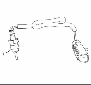
i04067589
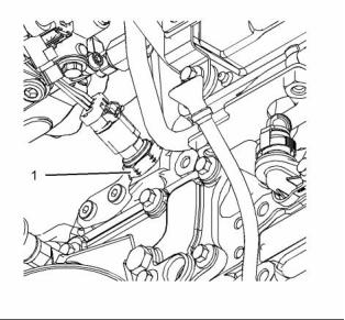
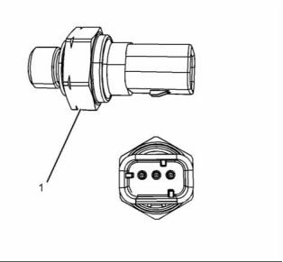
i03916100
Coolant Temperature Sensor
Engine Oil Pressure Sensor
g02285594
g02150747
Illustration 91
Illustration 92
Typical example
Typical example
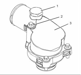
(1) Sensor
(1) Sensor
Torque for the sensor ............... 20 N·m (15 lb ft)
Tighten the sensor. Torque for the
sensor ....................................... 10 N·m (89 lb in)
This document is printed from SPI². Not for RESALE
![]()
![]()
![]()
KENR9123-01
45
Specifications Section
i03916119
i04285191
Boost Pressure Sensor
Atmospheric Pressure Sensor
g02150750
g02452158
Illustration 93
Illustration 95
Typical example
Typical example
(1) Tighten the atmospheric pressure sensor to the
following torque. ....................... 10 N·m (89 lb in)
g01332534
Illustration 94
Typical example
(1) Tighten the sensor to the following
torque. ......., ............................... 10 N·m (89 lb in)
This document is printed from SPI². Not for RESALE
![]()
![]()
![]()
![]()
46
KENR9123-01
Specifications Section
i03916112
Inlet Manifold Temperature
Sensor
g02154926
Illustration 97
Typical example
Note: Use tooling (A) in order to lubricate the thread
of temperature sensor (1).
(1) Tighten the temperature sensors to the following
torque. ...................................... 45 N·m (33 lb ft)
g02150749
Illustration 96
Typical example
i03996416
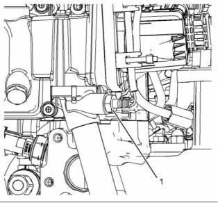
Pressure Sensor (NOx
Reduction System)
(1) Tighten the sensor to the following
torque. ...................................... 20 N·m (15 lb ft)
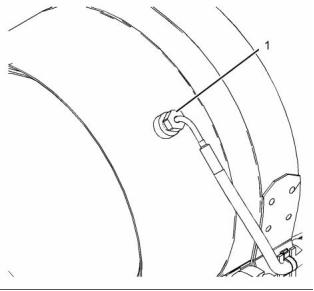
i04229390
Temperature Sensor (DPF
Inlet)
Table 12
Required Tools
Tool
Part Number
Part Description
Qty
Bostik Pure Nickel
Anti-Seize Compound
A
-
1
g02174143
Illustration 98
Typical example
This document is printed from SPI². Not for RESALE
![]()
![]()

![]()
![]()
KENR9123-01
47
Specifications Section
(1) Tighten the pressure sensors to the following
torque. ...................................... 10 N·m (89 lb in)
Operating voltage ........................................... 5 VDC
i04285189
i04285190
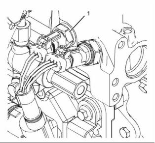
Temperature Sensor (NOx
Reduction System)
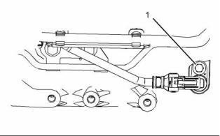
Speed/Timing Sensor
g01854256
Illustration 101
Typical example
g02452136
Illustration 99
Typical example
g02150748
Illustration 102
Typical example
(1) Tighten the bolt for the crankshaft position sensor
to the following torque. ............. 14 N·m (10 lb ft)
(2) Tighten the bolt for the camshaft position sensor
to the following torque. ............. 14 N·m (10 lb ft)
g02152917
Illustration 100
Typical example
(1) Tighten the sensor to the following
torque. ...................................... 30 N·m (22 lb ft)
This document is printed from SPI². Not for RESALE
![]()
![]()
![]()
![]()
![]()
48
KENR9123-01
Specifications Section
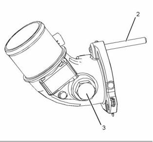
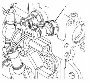
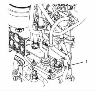
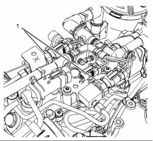
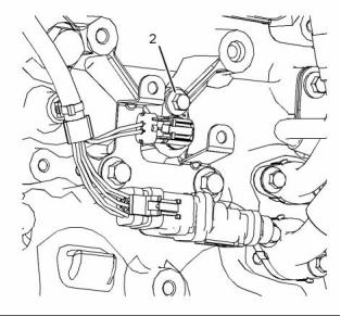
i04285193
i03918469
Electronic Control Module
Glow Plugs
g02465316
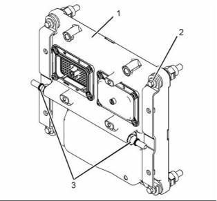
Illustration 103
Typical example
(1) Electronic control module (ECM)
(3) Fuel line connectors
g01861335
Illustration 104
(2) Bolt
Typical example
Tighten the four bolts for the ECM. Torque for the
bolts .......................................... 22 N·m (16 lb ft)
Tighten the glow plugs (2) in the cylinder head to the
following torque. ............................... 15 N·m (11 lb ft)
Tighten the nuts (1) for the bus bar (3) that is
installed on top of the glow plugs to the following
torque. ............................................... 2 N·m (18 lb in)
Tighten the nut (4) for the isolator for the bus bar to
the following torque. .......................... 6 N·m (53 lb in)
Voltage .................................................. 12 V or 24 V
This document is printed from SPI². Not for RESALE
![]()
![]()
![]()
KENR9123-01
49
Specifications Section
i03907009
(3) Tighten the bolts to the following torque. .. 16 N·m
(12 lb ft)
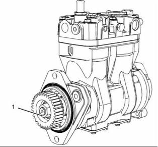
Air Compressor
(Twin Cylinder Compressor)
g02148381
Illustration 107
Typical example
(4) Tighten the bolts to the following torque. .. 22 N·m
(16 lb ft)
g02148379
Illustration 105
(5) Tighten the bolts to the following torque. .. 44 N·m
(32 lb ft)
Typical example
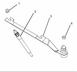
(1) Tighten the nut to the following torque. .. 120 N·m
(89 lb ft)
g02148408
Illustration 108
Typical example
g02148380
Illustration 106
(6) Tighten the banjo bolt to the following
Typical example
torque. ........................................ 9 N·m (80 lb in)
(2) Tighten the nuts to the following torque. .. 78 N·m
(58 lb ft)
For the correct procedure to install the air compressor,
refer to Disassembly and Assembly, “Air Compressor
- Remove and Install - Twin Cylinder Compressor”.
This document is printed from SPI². Not for RESALE
![]()
![]()
![]()
![]()
![]()
50
KENR9123-01
Specifications Section
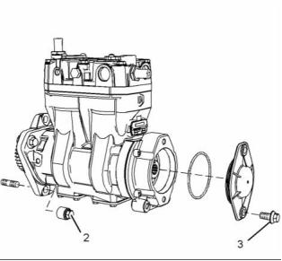
i03907068
(3) Tighten the bolts to the following torque. .. 13 N·m
(115 lb in)
Air Compressor
(Single Cylinder)
g02148447
Illustration 111
Typical example
(4) Tighten the bolts to the following torque. .. 22 N·m
(16 lb ft)
g02148439
Illustration 109
(5) Tighten the bolts to the following torque. .. 44 N·m
(32 lb ft)
Typical example
(1) Tighten the nut to the following torque. .. 120 N·m
(89 lb ft)
(6) Tighten the banjo bolt to the following
torque. ........................................ 9 N·m (80 lb in)
For the correct procedure to install the air compressor,
refer to Disassembly and Assembly, “Air Compressor
- Remove and Install - Single Cylinder”.
g02148442
Illustration 110
Typical example
(2) Tighten the nuts to the following torque. .. 78 N·m
(58 lb ft)
This document is printed from SPI². Not for RESALE
![]()
![]()
![]()
![]()
KENR9123-01
51
Index Section
Index
A
F
Accessory Drive..................................................... 36
Accessory Drive (SAE “B”) .................................... 36
Air Compressor (Single Cylinder).......................... 50
Air Compressor (Twin Cylinder Compressor)........ 49
Alternator............................................................... 42
Alternator Bracket .............................................. 42
The 12 V and 24 V Type 1 Alternators............... 42
Atmospheric Pressure Sensor............................... 45
Fan Drive............................................................... 41
Flexible Exhaust Pipe............................................ 22
Flywheel ................................................................ 39
Flywheel Housing .................................................. 39
Front Housing and Covers..................................... 37
Fuel Filter Base (Primary Fuel Filter Base) ...........
Fuel Filter Base (Single Secondary Fuel Filter
Base) ...................................................................
Fuel Filter Base (Twin Secondary Fuel Filter
Base) ...................................................................
Fuel Injection Lines................................................
Fuel Injection Pump...............................................
Fuel Injectors.........................................................
Fuel Manifold (Rail) ...............................................
Fuel Transfer Pump...............................................
8
7
7
4
5
6
8
6
B
Balancer Group ..................................................... 35
Belt Tensioner........................................................ 40
Boost Pressure Sensor.......................................... 45
C
G
Camshaft............................................................... 23
Camshaft Bearings................................................ 24
Connecting Rod..................................................... 32
Connecting Rod Bearing Journal........................... 31
Coolant Temperature Sensor................................. 44
Crankcase Breather............................................... 27
Crankshaft ............................................................ 29
Crankshaft Pulley .................................................. 40
Crankshaft Seals................................................... 31
Cylinder Block........................................................ 29
Cylinder Head........................................................ 12
Cylinder Head Valves ............................................ 11
Gear Group (Front)................................................ 37
Glow Plugs ............................................................ 48
I
Important Safety Information.................................
2
Inlet Manifold Temperature Sensor........................ 46
L
Lifter Group............................................................
9
D
M
Diesel Particulate Filter.......................................... 22
Main Bearing Journal............................................. 32
The shell for the main bearings.......................... 32
E
Electronic Control Module ..................................... 48
P
Engine Design.......................................................
4
Engine Lifting Bracket............................................ 41
Engine Oil Cooler .................................................. 25
Engine Oil Filter Base............................................ 24
Engine Oil Pan....................................................... 26
Front sealant...................................................... 26
Rear sealant....................................................... 26
Engine Oil Pressure............................................... 26
Engine Oil Pressure Sensor.................................. 44
Engine Oil Pump.................................................... 25
Exhaust Cooler (NRS)........................................... 19
Exhaust Gas Valve (NRS) ..................................... 17
Exhaust Manifold................................................... 21
Exhaust Sensor and Lines (NRS).......................... 18
Piston and Rings ................................................... 34
Piston................................................................. 34
Piston Cooling Jet.................................................. 35
Piston Cooling Jet Alignment............................. 35
Pressure Sensor (NOx Reduction System)........... 46
R
Refrigerant Compressor........................................ 41
Rocker Shaft..........................................................
9
S
Specifications Section ...........................................
4
This document is printed from SPI². Not for RESALE
![]()
Speed/Timing Sensor............................................ 47
Starter Motor.......................................................... 43
12 V Starting Motor 3 kW, 4 kW, and 24 V Starting
Motor 4.5 kW.................................................... 43
24 V Starting Motor 5.5 kW................................ 43
T
Table of Contents...................................................
3
Temperature Sensor (DPF Inlet)............................ 46
Temperature Sensor (NOx Reduction System) ..... 47
Turbocharger (Series Turbochargers) ................... 13
Turbocharger (Single Turbocharger) ..................... 15
V
Valve Mechanism Cover........................................ 10
W
Water Pump........................................................... 28
Water Temperature Regulator and Housing.......... 28
免費(fèi)熱線
400-100-8969???15088860848
400-100-8969???15088860848
機(jī)組銷售
0574-26871589? 15267810868
0574-26871589? 15267810868
配件銷售
0574-26886646? 15706865167
0574-26886646? 15706865167
維修熱線
0574-26871569 18658287286
0574-26871569 18658287286
手機(jī)端

微信公眾號
在線客服