 English
 Espaol
 Franais
 阿拉伯
阿拉伯 中文(簡(jiǎn))
 Deutsch
 Italiano
 Português
 日本
日本 韓國(guó)
 български
 hrvatski
 esky
esky Dansk
Dansk Nederlands
 suomi
suomi Ελληνικ
 印度
印度 norsk
norsk Polski
 Roman
Roman русский
 Svenska
 珀金斯Perkins2206-E13操作保養(yǎng)維修,珀金斯Perkins2206-E13操作保養(yǎng)維修技術(shù)支持中心,珀金斯Perkins2206-E13操作保養(yǎng)維修代理商,珀金斯Perkins2206-E13操作保養(yǎng)維修銷(xiāo)售服務(wù)中心,珀金斯Perkins2206-E13操作保養(yǎng)維修價(jià)格規(guī)格資料查詢(xún),寧波日昕動(dòng)力科技有限公司

首頁(yè)
產(chǎn)品展示>珀金斯Perkins2206-E13操作保養(yǎng)維修
珀金斯Perkins2206-E13操作保養(yǎng)維修
詳細(xì)描述
Operation and
Maintenance
Manual
2206-E13 Industrial Engine
TGB (Engine)
TGD (Engine)
TGF (Engine)
Table of Contents
Warranty Section
Warranty Information ............................................ 82
Foreword ................................................................. 4
Index Section
Safety Section
Index ..................................................................... 83
Safety Messages .................................................... 5
General Hazard Information ................................... 6
Burn Prevention ...................................................... 7
Fire Prevention and Explosion Prevention .............. 8
Crushing Prevention and Cutting Prevention .......... 9
Mounting and Dismounting ................................... 10
Before Starting Engine .......................................... 10
Engine Starting ..................................................... 10
Engine Stopping .................................................... 11
Electrical System ................................................... 11
Engine Electronics ................................................ 12
Product Information Section
General Information .............................................. 13
Model Views ......................................................... 14
Product Identification Information ........................ 17
Operation Section
Lifting and Storage ................................................ 21
Gauges and Indicators .......................................... 22
Features and Controls .......................................... 23
Engine Diagnostics ............................................... 29
Engine Starting ..................................................... 30
Engine Operation .................................................. 33
Engine Stopping ................................................... 34
Cold Weather Operation ....................................... 35
Maintenance Section
Refill Capacities .................................................... 38
Maintenance Interval Schedule ............................ 54
This document has been printed from SPI². Not for Resale
![]()
![]()
4
SEBU8337
Foreword
Foreword
Recommended service should be performed at the
appropriate intervals as indicated in the Maintenance
Interval Schedule. The actual operating environment
of the engine also governs the Maintenance Interval
Schedule. Therefore, under extremely severe,
dusty, wet or freezing cold operating conditions,
more frequent lubrication and maintenance than is
specified in the Maintenance Interval Schedule may
be necessary.
Literature Information
This manual contains safety, operation instructions,
lubrication and maintenance information. This
manual should be stored in or near the engine area
in a literature holder or literature storage area. Read,
study and keep it with the literature and engine
information.
The maintenance schedule items are organized for
a preventive maintenance management program. If
the preventive maintenance program is followed, a
periodic tune-up is not required. The implementation
of a preventive maintenance management program
should minimize operating costs through cost
avoidances resulting from reductions in unscheduled
downtime and failures.
English is the primary language for all Perkins
publications. The English used facilitates translation
and consistency.
Some photographs or illustrations in this manual
show details or attachments that may be different
from your engine. Guards and covers may have
been removed for illustrative purposes. Continuing
improvement and advancement of product design
may have caused changes to your engine which are
not included in this manual. Whenever a question
arises regarding your engine, or this manual, please
consult with your Perkins dealer or your Perkins
distributor for the latest available information.
Maintenance Intervals
Perform maintenance on items at multiples of
the original requirement. We recommend that the
maintenance schedules be reproduced and displayed
near the engine as a convenient reminder. We also
recommend that a maintenance record be maintained
as part of the engine’s permanent record.
Safety
Your authorized Perkins dealer or your Perkins
distributor can assist you in adjusting your
maintenance schedule to meet the needs of your
operating environment.
This safety section lists basic safety precautions.
In addition, this section identifies hazardous,
warning situations. Read and understand the basic
precautions listed in the safety section before
operating or performing lubrication, maintenance and
repair on this product.
Overhaul
Major engine overhaul details are not covered in
the Operation and Maintenance Manual except
for the interval and the maintenance items in that
interval. Major repairs should only be carried out by
Perkins authorized personnel. Your Perkins dealer
or your Perkins distributor offers a variety of options
regarding overhaul programs. If you experience
a major engine failure, there are also numerous
after failure overhaul options available. Consult with
your Perkins dealer or your Perkins distributor for
information regarding these options.
Operation
Operating techniques outlined in this manual are
basic. They assist with developing the skills and
techniques required to operate the engine more
efficiently and economically. Skill and techniques
develop as the operator gains knowledge of the
engine and its capabilities.
The operation section is a reference for operators.
Photographs and illustrations guide the operator
through procedures of inspecting, starting, operating
and stopping the engine. This section also includes a
discussion of electronic diagnostic information.
California Proposition 65 Warning
Diesel engine exhaust and some of its constituents
are known to the State of California to cause cancer,
birth defects, and other reproductive harm. Battery
posts, terminals and related accessories contain lead
and lead compounds. Wash hands after handling.
Maintenance
The maintenance section is a guide to engine care.
The illustrated, step-by-step instructions are grouped
by service hours and/or calendar time maintenance
intervals. Items in the maintenance schedule are
referenced to detailed instructions that follow.
This document has been printed from SPI². Not for Resale
![]()
SEBU8337
5
Safety Section
Safety Messages
Safety Section
i02767956
Safety Messages
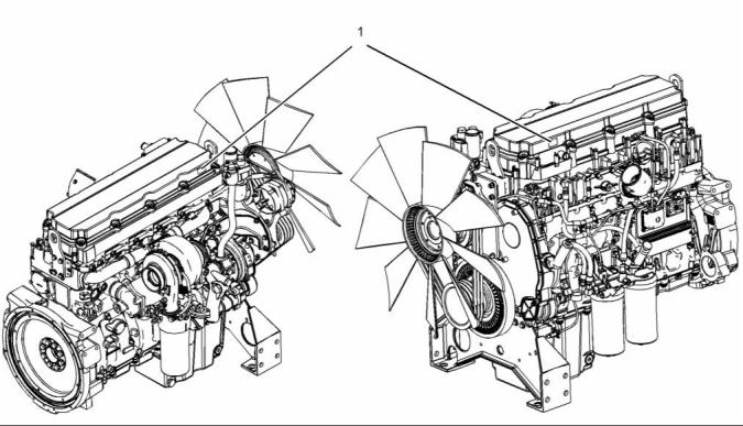
g01384682
Illustration 1
Location of safety message
There may be several specific safety messages on
your engine. The exact location and a description of
the safety messages are reviewed in this section.
Please become familiar with all safety messages.
Universal Warning (1)
The safety message for the universal warning is
located on both sides of the valve cover base.
Ensure that all of the safety messages are legible.
Clean the safety messages or replace the safety
messages if the words cannot be read or if the
illustrations are not visible. Use a cloth, water,
and soap to clean the safety messages. Do not
use solvents, gasoline, or other harsh chemicals.
Solvents, gasoline, or harsh chemicals could loosen
the adhesive that secures the safety messages. The
safety messages that are loosened could drop off
of the engine.
Replace any safety message that is damaged or
missing. If a safety message is attached to a part
of the engine that is replaced, install a new safety
message on the replacement part. Your Perkins
distributor can provide new safety messages.
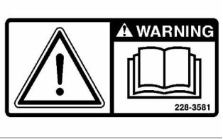
g00934493
Illustration 2
This document has been printed from SPI². Not for Resale
![]()
![]()
![]()
![]()
6
SEBU8337
Safety Section
General Hazard Information
Keep the engine free from foreign material. Remove
debris, oil, tools, and other items from the deck, from
walkways, and from steps.
Do not operate or work on this equipment unless
you have read and understand the instructions
and warnings in the Operation and Maintenance
Manuals. Failure to follow the instructions or
heed the warnings could result in serious injury
or death.
Never put maintenance fluids into glass containers.
Drain all liquids into a suitable container.
Obey all local regulations for the disposal of liquids.
Use all cleaning solutions with care.
Report all necessary repairs.
i02328435
General Hazard Information
Do not allow unauthorized personnel on the
equipment.
Ensure that the power supply is disconnected before
you work on the bus bar or the glow plugs.
Perform maintenance on the engine with the
equipment in the servicing position. Refer to the
OEM information for the procedure for placing the
equipment in the servicing position.
Pressure Air and Water
Pressurized air and/or water can cause debris
and/or hot water to be blown out. This could result in
personal injury.
g00104545
Illustration 3
The direct application of pressurized air or
pressurized water to the body could result in personal
injury.
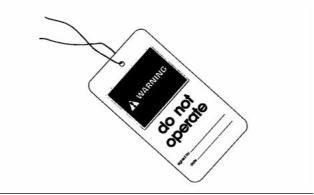
Attach a “Do Not Operate” warning tag or a similar
warning tag to the start switch or to the controls
before you service the equipment or before you
repair the equipment.
When pressurized air and/or water is used for
cleaning, wear protective clothing, protective shoes,
and eye protection. Eye protection includes goggles
or a protective face shield.
The maximum air pressure for cleaning purposes
must be below 205 kPa (30 psi). The maximum
water pressure for cleaning purposes must be below
275 kPa (40 psi).
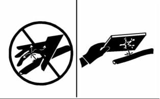
Fluid Penetration
Pressure can be trapped in the hydraulic circuit long
after the engine has been stopped. The pressure can
cause hydraulic fluid or items such as pipe plugs to
escape rapidly if the pressure is not relieved correctly.
g00702020
Illustration 4
Do not remove any hydraulic components or parts
until pressure has been relieved or personal injury
may occur. Do not disassemble any hydraulic
components or parts until pressure has been relieved
or personal injury may occur. Refer to the OEM
information for any procedures that are required to
relieve the hydraulic pressure.
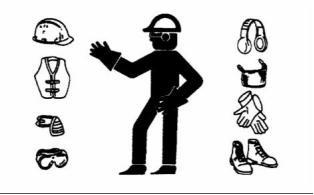
Wear a hard hat, protective glasses, and other
protective equipment, as required.
Do not wear loose clothing or jewelry that can snag
on controls or on other parts of the engine.
Make sure that all protective guards and all covers
are secured in place on the engine.
This document has been printed from SPI². Not for Resale
![]()
![]()
![]()
![]()
![]()
SEBU8337
7
Safety Section
Burn Prevention
Coolant
When the engine is at operating temperature, the
engine coolant is hot. The coolant is also under
pressure. The radiator and all lines to the heaters or
to the engine contain hot coolant. Any contact with
hot coolant or with steam can cause severe burns.
Allow cooling system components to cool before the
cooling system is drained.
Check the coolant level after the engine has stopped
and the engine has been allowed to cool. Ensure
that the filler cap is cool before removing the filler
cap. The filler cap must be cool enough to touch with
a bare hand. Remove the filler cap slowly in order
to relieve pressure.
g00687600
Illustration 5
Always use a board or cardboard when you check
for a leak. Leaking fluid that is under pressure can
penetrate body tissue. Fluid penetration can cause
serious injury and possible death. A pin hole leak can
cause severe injury. If fluid is injected into your skin,
you must get treatment immediately. Seek treatment
from a doctor that is familiar with this type of injury.
Cooling system conditioner contains alkali. Alkali can
cause personal injury. Do not allow alkali to contact
the skin, the eyes, or the mouth.
Oils
Hot oil and hot lubricating components can cause
personal injury. Do not allow hot oil or hot components
to contact the skin.
Containing Fluid Spillage
Care must be taken in order to ensure that fluids
are contained during performance of inspection,
maintenance, testing, adjusting and repair of the
engine. Make provision to collect the fluid with a
suitable container before any compartment is opened
or before any component is disassembled.
If the application has a makeup tank, remove the cap
for the makeup tank after the engine has stopped.
The filler cap must be cool to the touch.
Batteries
The liquid in a battery is an electrolyte. Electrolyte is
an acid that can cause personal injury. Do not allow
electrolyte to contact the skin or the eyes.
• Only use the tools that are suitable for collecting
fluids and equipment that is suitable for collecting
fluids.
Do not smoke while checking the battery electrolyte
levels. Batteries give off flammable fumes which can
explode.
• Only use the tools that are suitable for containing
fluids and equipment that is suitable for containing
fluids.
Always wear protective glasses when you work with
batteries. Wash hands after touching batteries. The
use of gloves is recommended.
Obey all local regulations for the disposal of liquids.
i02088921
Burn Prevention
Do not touch any part of an operating engine.
Allow the engine to cool before any maintenance
is performed on the engine. Relieve all pressure in
the appropriate system before any lines, fittings or
related items are disconnected.
This document has been printed from SPI². Not for Resale
![]()
![]()
8
SEBU8337
Safety Section
Fire Prevention and Explosion Prevention
Exhaust shields (if equipped) protect hot exhaust
i02813488
components from oil or fuel spray in case of a line,
a tube, or a seal failure. Exhaust shields must be
installed correctly.
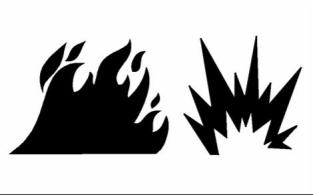
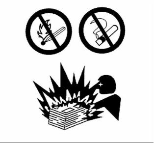
Fire Prevention and Explosion
Prevention
Do not weld on lines or tanks that contain flammable
fluids. Do not flame cut lines or tanks that contain
flammable fluid. Clean any such lines or tanks
thoroughly with a nonflammable solvent prior to
welding or flame cutting.
Wiring must be kept in good condition. All electrical
wires must be correctly routed and securely attached.
Check all electrical wires daily. Repair any wires
that are loose or frayed before you operate the
engine. Clean all electrical connections and tighten
all electrical connections.
Eliminate all wiring that is unattached or unnecessary.
Do not use any wires or cables that are smaller than
the recommended gauge. Do not bypass any fuses
and/or circuit breakers.
g00704000
Illustration 6
Arcing or sparking could cause a fire. Secure
connections, recommended wiring, and correctly
maintained battery cables will help to prevent arcing
or sparking.
All fuels, most lubricants, and some coolant mixtures
are flammable.
Flammable fluids that are leaking or spilled onto hot
surfaces or onto electrical components can cause
a fire. Fire may cause personal injury and property
damage.
Inspect all lines and hoses for wear or for
deterioration. The hoses must be correctly routed.
The lines and hoses must have adequate support
and secure clamps. Tighten all connections to the
recommended torque. Leaks can cause fires.
A flash fire may result if the covers for the engine
crankcase are removed within fifteen minutes after
an emergency shutdown.
Oil filters and fuel filters must be correctly installed.
The filter housings must be tightened to the correct
torque.
Determine whether the engine will be operated in an
environment that allows combustible gases to be
drawn into the air inlet system. These gases could
cause the engine to overspeed. Personal injury,
property damage, or engine damage could result.
If the application involves the presence of combustible
gases, consult your Perkins dealer and/or your
Perkins distributor for additional information about
suitable protection devices.
Remove all flammable combustible materials or
conductive materials such as fuel, oil, and debris from
the engine. Do not allow any flammable combustible
materials or conductive materials to accumulate on
the engine.
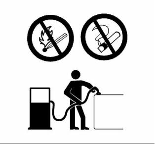
Store fuels and lubricants in correctly marked
containers away from unauthorized persons. Store
oily rags and any flammable materials in protective
containers. Do not smoke in areas that are used for
storing flammable materials.
Do not expose the engine to any flame.
g00704059
Illustration 7
This document has been printed from SPI². Not for Resale
![]()
![]()
![]()
SEBU8337
9
Safety Section
Crushing Prevention and Cutting Prevention
Use caution when you are refueling an engine. Do
not smoke while you are refueling an engine. Do not
refuel an engine near open flames or sparks. Always
stop the engine before refueling.
Lines, Tubes and Hoses
Do not bend high pressure lines. Do not strike high
pressure lines. Do not install any lines that are bent
or damaged. Do not clip any other items to the high
pressure lines.
Repair any lines that are loose or damaged. Leaks
can cause fires. Consult your Perkins dealer or your
Perkins distributor for repair or for replacement parts.
Check lines, tubes and hoses carefully. Do not use
your bare hand to check for leaks. Use a board or
cardboard to check for leaks. Tighten all connections
to the recommended torque.
Replace the parts if any of the following conditions
are present:
• End fittings are damaged or leaking.
• Outer coverings are chafed or cut.
• Wires are exposed.
• Outer coverings are ballooning.
• Flexible part of the hoses are kinked.
• Outer covers have embedded armoring.
• End fittings are displaced.
g00704135
Illustration 8
Gases from a battery can explode. Keep any open
flames or sparks away from the top of a battery. Do
not smoke in battery charging areas.
Never check the battery charge by placing a metal
object across the terminal posts. Use a voltmeter or
a hydrometer.
Make sure that all clamps, guards, and heat shields
are installed correctly. During engine operation, this
will help to prevent vibration, rubbing against other
parts, and excessive heat.
Incorrect jumper cable connections can cause
an explosion that can result in injury. Refer to
the Operation Section of this manual for specific
instructions.
i01359666
Crushing Prevention and
Cutting Prevention
Do not charge a frozen battery. This may cause an
explosion.
The batteries must be kept clean. The covers
(if equipped) must be kept on the cells. Use the
recommended cables, connections, and battery box
covers when the engine is operated.
Support the component properly when work beneath
the component is performed.
Fire Extinguisher
Unless other maintenance instructions are provided,
never attempt adjustments while the engine is
running.
Make sure that a fire extinguisher is available. Be
familiar with the operation of the fire extinguisher.
Inspect the fire extinguisher and service the fire
extinguisher regularly. Obey the recommendations
on the instruction plate.
Stay clear of all rotating parts and of all moving
parts. Leave the guards in place until maintenance
is performed. After the maintenance is performed,
reinstall the guards.
Keep objects away from moving fan blades. The fan
blades will throw objects or cut objects.
This document has been printed from SPI². Not for Resale
![]()
![]()
10
SEBU8337
Safety Section
Mounting and Dismounting
When objects are struck, wear protective glasses in
order to avoid injury to the eyes.
If equipped, ensure that the lighting system for the
engine is suitable for the conditions. Ensure that all
lights work correctly, if equipped.
Chips or other debris may fly off objects when objects
are struck. Before objects are struck, ensure that no
one will be injured by flying debris.
All protective guards and all protective covers must
be installed if the engine must be started in order
to perform service procedures. To help prevent an
accident that is caused by parts in rotation, work
around the parts carefully.
i01372247
Mounting and Dismounting
Do not bypass the automatic shutoff circuits. Do not
disable the automatic shutoff circuits. The circuits are
provided in order to help prevent personal injury. The
circuits are also provided in order to help prevent
engine damage.
Inspect the steps, the handholds, and the work area
before mounting the engine. Keep these items clean
and keep these items in good repair.
See the Service Manual for repairs and for
adjustments.
Mount the engine and dismount the engine only at
locations that have steps and/or handholds. Do not
climb on the engine, and do not jump off the engine.
i02583384
Face the engine in order to mount the engine or
dismount the engine. Maintain a three-point contact
with the steps and handholds. Use two feet and one
hand or use one foot and two hands. Do not use any
controls as handholds.
Engine Starting
Do not stand on components which cannot support
your weight. Use an adequate ladder or use a work
platform. Secure the climbing equipment so that the
equipment will not move.
Do not use aerosol types of starting aids such as
ether. Such use could result in an explosion and
personal injury.
Do not carry tools or supplies when you mount the
engine or when you dismount the engine. Use a hand
line to raise and lower tools or supplies.
If a warning tag is attached to the engine start switch
or to the controls DO NOT start the engine or move
the controls. Consult with the person that attached
the warning tag before the engine is started.
i02813489
All protective guards and all protective covers must
be installed if the engine must be started in order
to perform service procedures. To help prevent an
accident that is caused by parts in rotation, work
around the parts carefully.
Before Starting Engine
Before the initial start-up of an engine that is new,
serviced or repaired, make provision to shut the
engine off, in order to stop an overspeed. This may
be accomplished by shutting off the air and/or fuel
supply to the engine.
Start the engine from the operator’s compartment or
from the engine start switch.
Always start the engine according to the procedure
that is described in the Operation and Maintenance
Manual, “Engine Starting” topic in the Operation
Section. Knowing the correct procedure will help to
prevent major damage to the engine components.
Knowing the procedure will also help to prevent
personal injury.
Overspeed shutdown should occur automatically for
engines that are controlled electronically. If automatic
shutdown does not occur, press the emergency stop
button in order to cut the fuel and/or air to the engine.
Inspect the engine for potential hazards.
To ensure that the jacket water heater (if equipped)
is working correctly, check the water temperature
gauge and/or the oil temperature gauge during the
heater operation.
Before starting the engine, ensure that no one is on,
underneath, or close to the engine. Ensure that the
area is free of personnel.
This document has been printed from SPI². Not for Resale
![]()
![]()
![]()
SEBU8337
11
Safety Section
Engine Stopping
Engine exhaust contains products of combustion
which can be harmful to your health. Always start the
engine and operate the engine in a well ventilated
area. If the engine is started in an enclosed area,
vent the engine exhaust to the outside.
Check the electrical wires daily for wires that
are loose or frayed. Tighten all loose electrical
connections before the engine is started. Repair all
frayed electrical wires before the engine is started.
See the Operation and Maintenance Manual for
specific starting instructions.
Note: The engine may be equipped with a device for
cold starting. If the engine will be operated in very
cold conditions, then an extra cold starting aid may
be required. Normally, the engine will be equipped
with the correct type of starting aid for your region
of operation.
Grounding Practice
i01462046
Engine Stopping
Stop the engine according to the procedure in
the Operation and Maintenance Manual, “Engine
Stopping (Operation Section)” in order to avoid
overheating of the engine and accelerated wear of
the engine components.
Use the Emergency Stop Button (if equipped) ONLY
in an emergency situation. Do not use the Emergency
Stop Button for normal engine stopping. After an
emergency stop, DO NOT start the engine until the
problem that caused the emergency stop has been
corrected.
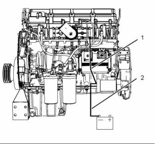
g01403749
Illustration 9
Typical example
Stop the engine if an overspeed condition occurs
during the initial start-up of a new engine or an engine
that has been overhauled. This may be accomplished
by shutting off the fuel supply to the engine and/or
shutting off the air supply to the engine.
(1) Starting motor to engine block
(2) Starting motor to battery negative
Correct grounding for the engine electrical system
is necessary for optimum engine performance
and reliability. Incorrect grounding will result in
uncontrolled electrical circuit paths and in unreliable
electrical circuit paths.
To stop an electronically controlled engine, cut the
power to the engine.
Uncontrolled electrical circuit paths can result in
damage to the crankshaft bearing journal surfaces
and to aluminum components.
i02814681
Electrical System
Engines that are installed without engine-to-frame
ground straps can be damaged by electrical
discharge.
Never disconnect any charging unit circuit or battery
circuit cable from the battery when the charging unit
is operating. A spark can cause the combustible
gases that are produced by some batteries to ignite.
To ensure that the engine and the engine electrical
systems function correctly, an engine-to-frame
ground strap with a direct path to the battery must be
used. This path may be provided by way of a direct
engine ground to the frame.
To help prevent sparks from igniting combustible
gases that are produced by some batteries, the
negative “−” cable should be connected last from the
external power source to the negative “−” terminal
of the starting motor. If the starting motor is not
equipped with a negative “−” terminal, connect the
cable to the engine block.
The connections for the grounds should be tight and
free of corrosion. The engine alternator must be
grounded to the negative “-” battery terminal with
a wire that is adequate to handle the full charging
current of the alternator.
This document has been printed from SPI². Not for Resale
![]()
![]()
12
SEBU8337
Safety Section
Engine Electronics
The power supply connections and the ground
connections for the engine electronics should always
be from the isolator to the battery.
i02773399
Engine Electronics
Tampering with the electronic system installation
or the OEM wiring installation can be dangerous
and could result in personal injury or death and/or
engine damage.
This engine has a comprehensive, programmable
Engine Monitoring System. The Engine Control
Module (ECM) has the ability to monitor the engine
operating conditions. If any of the engine parameters
extend outside an allowable range, the ECM will
initiate an immediate action.
The following actions are available for engine
monitoring control: WARNING, ACTION ALERT, and
SHUTDOWN.
Many of the parameters that are monitored by the
ECM can be programmed for the engine monitoring
functions. The following parameters can be monitored
as a part of the Engine Monitoring System:
• Atmospheric Pressure
• Intake Manifold Air Pressure
• Coolant Temperature
• Engine Oil Pressure
• Crankshaft Position
• Camshaft Position
• Fuel Temperature
• Intake Manifold Temperature
• System Voltage
The Engine Monitoring package can vary for different
engine models and different engine applications.
However, the monitoring system and the engine
monitoring control will be similar for all engines.
This document has been printed from SPI². Not for Resale
![]()
![]()
![]()
SEBU8337
13
Product Information Section
General Information
Product Information
Section
General Information
i01889424
Welding on Engines with
Electronic Controls
NOTICE
Proper welding procedures are necessary in order
to avoid damage to the engine’s ECM, sensors, and
associated components. When possible, remove the
component from the unit and then weld the compo-
nent. If removal of the component is not possible,
the following procedure must be followed when you
weld with a unit that is equipped with an Electronic
Engine. The following procedure is considered to be
the safest procedure to weld a component. This pro-
cedure should provide a minimum risk of damage to
electronic components.
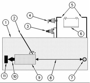
g00765012
Illustration 10
Use the example above. The current flow from the welder to
the ground clamp of the welder will not cause damage to any
associated components.
(1) Engine
(2) Welding rod
(3) Keyswitch in the OFF position
(4) Battery disconnect switch in the open position
(5) Disconnected battery cables
(6) Battery
NOTICE
(7) Electrical/Electronic component
(8) Maximum distance between the component that is being
welded and any electrical/electronic component
(9) The component that is being welded
(10) Current path of the welder
(11) Ground clamp for the welder
Do not ground the welder to electrical components
such as the ECM or sensors. Improper grounding can
cause damage to the drive train bearings, hydraulic
components, electrical components, and other com-
ponents.
4. Connect the welding ground cable directly to the
part that will be welded. Place the ground cable as
close as possible to the weld in order to reduce the
possibility of welding current damage to bearings,
hydraulic components, electrical components, and
ground straps.
Clamp the ground cable from the welder to the com-
ponent that will be welded. Place the clamp as close
as possible to the weld. This will help reduce the pos-
sibility of damage.
1. Stop the engine. Turn the switched power to the
OFF position.
Note: If electrical/electronic components are used
as a ground for the welder, or electrical/electronic
components are located between the welder ground
and the weld, current flow from the welder could
severely damage the component.
2. Disconnect the negative battery cable from the
battery. If a battery disconnect switch is provided,
open the switch.
5. Protect the wiring harness from welding debris
and spatter.
3. Disconnect the J1/P1 connectors from the ECM.
Move the harness to a position that will not allow
the harness to accidentally move back and make
contact with any of the ECM pins.
6. Use standard welding practices to weld the
materials.
This document has been printed from SPI². Not for Resale
![]()
![]()
![]()
![]()
![]()
![]()
![]()
14
SEBU8337
Product Information Section
Model Views
Model Views
i02770579
Model View Illustrations
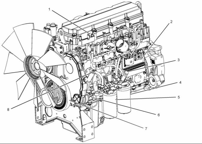
g01385634
Illustration 11
Typical example
Left side engine view
(1) Connection for the breather
(2) Electronic control module (ECM)
(3) Fuel priming pump
(4) Secondary fuel filter
(5) Primary fuel filter
(6) Fuel pump
(7) Crankshaft damper
(8) Oil filler
This document has been printed from SPI². Not for Resale
![]()
![]()
SEBU8337
15
Product Information Section
Model Views
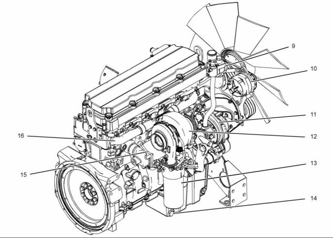
g01385635
Illustration 12
Typical example
Right side engine view
(9) Water temperature regulator housing
(10) Alternator
(12) Turbocharger
(13) Oil filter
(15) Oil cooler
(16) Exhaust manifold
(11) Water pump
(14) Oil drain plug
The electronic engines that are covered by this
manual have the following characteristics: direct fuel
injection, electronic unit injection that is mechanically
actuated, turbocharged, and air-to-air aftercooled
(ATAAC).
i02770677
Engine Description
Table 1
The electronic engine control system provides the
following functions: electronic governing, automatic
air to fuel ratio control, injection timing control, and
system diagnostics.
2206 Engine Specifications
Cylinders and Arrangement
Bore
In-line six cylinder
130 mm (5.2 inch)
157 mm (6.2 inch)
An electronic governor controls the output of the unit
injectors in order to maintain the engine rpm that is
desired.
Stroke
Displacement
Firing Order
12.5 L (763 in )
3
1-5-3-6-2-4
Rotation (flywheel end)
Counterclockwise
This document has been printed from SPI². Not for Resale
![]()
![]()
16
SEBU8337
Product Information Section
Model Views
Very high injection pressures are produced by
electronically controlled, mechanically actuated unit
injectors. The injectors combine the pumping and the
electronic fuel metering (duration and timing) during
injection. The unit injectors accurately control smoke
limiting, white smoke, and engine acceleration rates.
Engine efficiency, efficiency of emission controls, and
engine performance depend on adherence to proper
operation and maintenance recommendations. This
includes the use of recommended fuels, coolants
and lubrication oils.
Aftermarket Products and Perkins
Engines
There is one unit injector per cylinder. Individual unit
injectors meter the fuel. The individual unit injectors
also pump the fuel. The metering and the pumping is
done under high pressure. High injection pressures
help to reduce fuel consumption and emissions.
The use of this type of unit injector provides total
electronic control of injection timing. The injection
timing varies with engine operating conditions. The
engine performance is optimized in the following
areas:
When auxiliary devices, accessories, or consumables
(filters, additives, catalysts, etc) which are made by
other manufacturers are used on Perkins products,
the Perkins warranty is not affected simply because
of such use.
However, failures that result from the installation
or use of other manufacturers’ devices,
accessories, or consumables are NOT Perkins
defects. Therefore, the defects are NOT covered
under the Perkins warranty.
• Starting
• Emissions
• Noise
• Fuel consumption
The timing advance is achieved through precise
control of the injector firing. Engine speed is
controlled by adjusting the firing duration. The
information is provided to the Electronic Control
Module (ECM) by the crankshaft position sensor and
the camshaft position sensor. The information is for
detection of cylinder position and engine speed.
The engines have built-in diagnostics in order to
ensure that all of the components are functioning
and operating properly. In the event of a system
component deviation from the programmed limits,
the operator will be alerted to the condition by a
DIAGNOSTIC lamp that is mounted on the control
panel. An electronic service tool that is provided by
Perkins may be used to read the diagnostic codes.
These codes are logged and stored in the ECM.
Refer to Operation and Maintenance Manual, “Engine
Diagnostics” for additional information.
The cooling system consists of the following items:
a centrifugal pump that is driven by a gear, water
temperature regulator, an oil cooler, and a radiator
that incorporates a shunt system.
The engine lubricating oil is supplied by a gear
type pump. The engine lubricating oil is cooled and
filtered. Bypass valves provide unrestricted flow
of lubrication oil to the engine parts when the oil
viscosity is high or if either the oil cooler or the oil
filter elements (paper cartridge) become plugged.
This document has been printed from SPI². Not for Resale
![]()
SEBU8337
17
Product Information Section
Product Identification Information
Product Identification
Information
i02770689
Plate Locations and Film
Locations
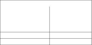
g01385686
Illustration 13
(1) Serial number plate
Perkins engines are identified by serial numbers.
These numbers are shown on the engine serial
number plate. Perkins distributors need these
numbers in order to determine the components that
were included with the engine. This permits accurate
identification of replacement part numbers.
This document has been printed from SPI². Not for Resale
![]()
![]()
![]()
18
SEBU8337
Product Information Section
Product Identification Information
Serial Number Plate (1)
Total Lubrication System Capacity _____________________
Total Cooling System Capacity _________________________
Air Cleaner Element _______________________________________
Fan Drive Belt ______________________________________________
Alternator Belt ______________________________________________
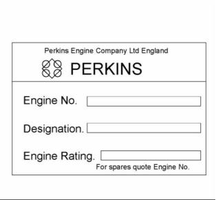
g01403841
Illustration 14
Typical example
The engine serial number plate is located on the right
side of the engine block.
Engine serial number _____________________________________
Designation _________________________________________________
Engine Rating ______________________________________________
i02563635
Reference Numbers
Information for the following items may be needed to
order parts. Locate the information for your engine.
Record the information in the appropriate space.
Make a copy of this list for a record. Keep the
information for future reference.
Record for Reference
Engine Model _______________________________________________
Engine Serial number _____________________________________
Engine rpm __________________________________________________
Primary Fuel Filter _________________________________________
Secondary Fuel Filter Element __________________________
Lubrication Oil Filter Element ___________________________
This document has been printed from SPI². Not for Resale
![]()
![]()
SEBU8337
19
Product Information Section
Product Identification Information
i02770895
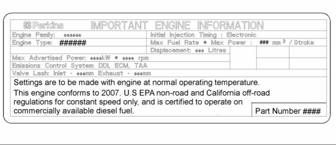
Emissions Certification Film
g01385765
Illustration 15
Typical example
The emission certification film is located on the left
hand side of the valve mechanism cover.
Programmable Monitoring System
(PMS)
The Programmable Monitoring System determines
the level of action that is taken by the ECM in
response to a condition that can damage the engine.
These conditions are identified by the ECM from the
signals that are produced from the following sensors.
i02817239
Customer Specified
Parameters
• Inlet Manifold Temperature Sensor
• Coolant Temperature Sensor
• Engine Oil Pressure Sensor
• Engine Crankshaft/Camshaft Sensors
• Inlet Manifold Pressure Sensor
• Fuel Temperature Sensor
To record programmed specifications, use the
following blanks.
Customer Passwords (If required).
• First Password ___________________________________________
• Second Password ______________________________________
Rating Selection (L-N) __________________________________
Equipment ID ______________________________________________
This document has been printed from SPI². Not for Resale
![]()
![]()
20
SEBU8337
Product Information Section
Product Identification Information
Table 2
Event Code
Parameter
State
Trip Point
Delay Time
E162
-1
High Boost Pressure
Warn Operator (1)
On
300 kPa (43.5 psi) 60 seconds
-2
Action Alert (2)
Always On
Map
5 seconds
E360
-1
Low Engine Oil Pressure
Warn Operator (1)
On
200 kPa (29 psi)
60 seconds
2 seconds
2 seconds
-2
Action Alert (2)
Always On
Always On
Map
Map
-3
Engine Shutdown (3)
High Engine Coolant Temperature
Warn Operator (1)
E361
-1
On
104 °C (2190 °F)
105 °C (221 °F)
108 °C (226 °F)
60 seconds
10 seconds
10 seconds
-2
Action Alert (2)
Always On
Always On
-3
Engine Shutdown (3)
Engine Overspeed
Warn Operator (1)
E362
-1
On
2000 RPM
2050 RPM
2140 RPM
1 second
0 second
0 second
-2
Action Alert (2)
Always On
Always On
-3
Engine Shutdown (3)
High Fuel Supply Temperature
Warn Operator (1)
E363
-1
On
60 °C (140 °F)
68 °C (154 °F)
60 seconds
60 seconds
-2
Action Alert (2)
Always On
E368
-1
High Engine Intake Manifold Air Temperature
Warn Operator (1)
Action Alert (2)
On
75 °C (167 °F)
78 °C (172 °F)
60 seconds
10 seconds
-2
Always On
Refer to Troubleshooting , “System Configuration
Parameters” for additional information for the
Programmable Monitoring System.
This document has been printed from SPI². Not for Resale
![]()

SEBU8337
21
Operation Section
Lifting and Storage
Operation Section
Lifting and Storage
i02848873
Product Storage
Refer to Perkins Engine Company limited, Stafford
for information on engine storage.
i02513632
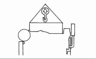
Product Lifting
There is three different levels of engine storage.
Level “A, B and C”.
Level “A ”
Level “A” will give protection for 12 month for diesel
engines and 12 month protection for gas engines.
This is for engines that are transported by a container
or a truck. Level “A” is for the transportation of items
that are within the United kingdom and within Europe.
Level “B ”
This level is additional to level “A”. Level “B ” will
give protection under normal storage condition
from −15° to +55°C (5° to 99°F) and “90%”
relative humidity for two year. Level “B” is for the
transportation of items overseas.
g00103219
Illustration 16
NOTICE
Level “C ”
Never bend the eyebolts and the brackets. Only load
the eyebolts and the brackets under tension. Remem-
ber that the capacity of an eyebolt is less as the angle
between the supporting members and the object be-
comes less than 90 degrees.
In order to protect the product to Level “C”, contact
Perkins Engines Company Limited Stafford.
When it is necessary to remove a component at an
angle, only use a link bracket that is properly rated for
the weight.
Use a hoist to remove heavy components. Use
an adjustable lifting beam to lift the engine. All
supporting members (chains and cables) should be
parallel to each other. The chains and cables should
be perpendicular to the top of the object that is being
lifted.
Some removals require lifting the fixtures in order to
obtain proper balance and safety.
To remove the engine ONLY, use the lifting eyes that
are on the engine.
Lifting eyes are designed and installed for specific
engine arrangements. Alterations to the lifting eyes
and/or the engine make the lifting eyes and the lifting
fixtures obsolete. If alterations are made, ensure
that proper lifting devices are provided. Consult your
Perkins dealer for information regarding fixtures for
proper engine lifting.
This document has been printed from SPI². Not for Resale
![]()
![]()
![]()
![]()
![]()
22
SEBU8337
Operation Section
Gauges and Indicators
Gauges and Indicators
i02773410
Gauges and Indicators
Your engine may not have the same gauges or all of
the gauges that are described. For more information
about the gauge package, see the OEM information.
Gauges provide indications of engine performance.
Ensure that the gauges are in good working order.
Determine the normal operating range by observing
the gauges over a period of time.
Noticeable changes in gauge readings indicate
potential gauge or engine problems. Problems may
also be indicated by gauge readings that change
even if the readings are within specifications.
Determine and correct the cause of any significant
change in the readings. Consult your Perkins
distributor for assistance.
NOTICE
If no oil pressure is indicated, STOP the engine. If
maximum coolant temperature is exceeded, STOP
the engine. Engine damage can result.
Engine Oil Pressure – The range for the
engine oil pressure is 420 kPa (61 psi).
Jacket Water Coolant Temperature –
Typical water temperature into the engine
is 88 °C (190 °F). Higher temperatures
may occur under certain conditions. The water
temperature reading may vary according to load. The
reading should never exceed 107 °C (224 °F).
1. A high water temperature switch is installed in the
cooling system.
Tachometer – This gauge indicates engine
speed (rpm).
Ammeter – This gauge indicates the
amount of charge or discharge in the
battery charging circuit. Operation of the
indicator should be to the right side of “0” (zero).
Service Hour Meter – The gauge indicates
operating hours of the engine.
This document has been printed from SPI². Not for Resale
![]()
![]()
![]()
![]()
![]()
![]()
![]()
![]()
SEBU8337
23
Operation Section
Features and Controls
Features and Controls
Warning Alarm
The Warning alarm informs the user that the engine
is approaching a critical condition.
i02780670
Monitoring System
If the engine is in the Warning condition, then the
event will be logged in the memory of the ECM.
A event code will be transmitted over the Perkins
Data link and the hard wired Warning output will be
energized. If the engine is in the Warning condition,
the event code and output will remain while the
condition exists. The electronic service tool is used to
remove the event code from the memory of the ECM.
The trip point for the Warning alarm will be set to a
factory default in production. The electronic service
tool may be used to alter the trip point for a Warning
within predefined limits.
The engine has protection in three stages:
• Warning
• Action Alert
• Shutdown
The engine protection may be overridden by the
critical condition mode.
Action Alert
The Electronic Control Module (ECM) monitors the
following parameters:
The Action Alert informs the OEM that the engine is
approaching a critical condition. The engine should
be stopped in a controlled manner. Further running of
the engine may result in an immediate shutdown.
• Engine Temperatures
• Engine Pressures
• Engine Speed
If the engine is in the Action Alert condition, the event
will be logged in the memory of the ECM. A event
code will be transmitted over the Perkins Data link
and the hard wired Action Alert will be energized. If
the engine is in the Action Alert condition the event
code and output will remain while the condition exists.
The event code can not be cleared from the memory
of the ECM without using a factory password.
If the parameters exceed a trip point for a period of
time that is longer than the delay period, the ECM
logs an event code and the indicator switches ON.
The following parameters are monitored for event
codes:
Shutdown
• Lubricating Oil Pressure
• Coolant Temperature
• Overspeed
If the engine reaches the Shutdown condition,one of
the following events has occurred: low lubricating oil
pressure, high coolant temperature or overspeed.
The event will be logged in the memory of the ECM.
The engine will be shut down. A event code will
be transmitted over the Perkins Data link and the
hard wired Shutdown output will be energized. The
Shutdown condition will latch until the ECM is reset.
The event code for the shutdown can not be cleared
from the memory of the ECM without using a factory
password.
• Intake Manifold Temperature
• Intake Manifold Pressure
• Fuel Temperature
The temperature protection is disabled for a period
of time when the engine is cranking in order to
compensate for heat soak solutions.
Critical Protection Override
If the engine is in an application that is critical for
safety, the protection system can be overridden in
order to ensure the continuation of the power supply
during engine fault conditions.
The ECM has dedicated alarm outputs for each of the
three stages of protection. There are also dedicated
alarm outputs for oil pressure, coolant temperature
and overspeed events which are energized at any
stage of protection.
This document has been printed from SPI². Not for Resale
![]()
24
SEBU8337
Operation Section
Features and Controls
Shutdown Reset
Critical Protection Override will be set by a switch
input from the OEM. For example, this may be
a switch to battery + in order to disable a critical
override. Critical Protection Override input can be
enabled in the electronic service tool by use of a
factory password.
The cause of an engine shutdown must be
investigated. Corrective action must be taken before
the system is reset in order to operate the engine.
After an engine shutdown, operate the reset input of
the ECM or power down the controller.
When the Critical Protection Override feature is
active, the ECM will continue to run the engine in all
shutdown conditions with the exception of Overspeed
shutdown. If the shutdown is overridden a event code
is generated. The ECM will log the event code. The
ECM will energize the following: Warning, Action
Alert, Shutdown, oil pressure, coolant temperature,
and overspeed outputs as normal. The warranty of
the engine will be invalidated if the engine is operated
in the following conditions: active event code and
Critical Protection Override mode.
Powering down the electronic control module can be
achieved by the operation of the keyswitch into sleep
mode. The electronic control module can be powered
down by isolating the power supply to the electronic
control module.
Note: It is not possible to reset the ECM by using the
Reset input until the engine has come to rest.
Altitude derate
Standard Warning Outputs
At high altitudes or high ambient temperatures, the
engine will be derated. The engine derate information
can be obtained from the Applications Department at
Perkins Engines Company Limited Stafford.
The ECM provides individual outputs in order to
drive warning lamps or relays to indicate each of the
following fault conditions:
• Diagnostic Fault
• Oil Pressure
• Coolant Temperature
• Overspeed
Diagnostic
If there is a fault with an engine protection sensor on
the engine, the engine activates a diagnostic code.
The engine communicates the diagnostic code to the
operator via the Diagnostic output. The diagnostic
code provides an indication to the operator of a fault
with the engine protection system. Running of the
engine for a prolonged period in this condition may
result in engine failure. The output is generally used
to drive lamps or relays.
• Action Alert
• Warning
• Shutdown
The following sensors are monitored in order to
determine if the sensors are out of the normal range,
an open circuit or a short circuit:
If the ECM detects a warning for the coolant
temperature , the output on the coolant temperature
will be energized and the warning output will be
energized. If the ECM detects a warning for the low
oil pressure, the output on the oil pressure will be
energized and the warning output will be energized.
• Atmosphere Pressure
• Lubricating Oil Pressure
• Inlet Manifold Pressure
• Inlet Manifold Temperature
• Fuel Temperature
If the Action Alert alarms are enabled and the ECM
detects a coolant temperature condition, the output
on the coolant Temperature will be energized and the
output on the Action Alert will be energized.
If the engine shuts down on low oil pressure the
output on the low oil pressure will be energized and
the output on the shutdown will be energized. If the
engine shuts down on coolant temperature or the
engine shuts down on overspeed the dedicated
output and the shutdown output will be energized.
• Coolant Temperature
• Engine Speed
• Desired Speed Input
This document has been printed from SPI². Not for Resale
![]()
SEBU8337
25
Operation Section
Features and Controls
The Diagnostic output differs from the Warning and
Shutdown outputs. The Warning and Shutdown
outputs refer to the operation of the engine. The
Diagnostic output refers to the condition of the
electronic system and software system.
A diagnostic fault may develop on the lubricating
oil pressure or coolant temperature sensors. For
example, if a Shutdown protection sensor has a fault,
this will result in an engine shutdown, unless the
system is in critical protection override. If a diagnostic
fault occurs with one of the engine speed sensors
while the engine is running. The engine continues to
run by using the other timing sensor for reference.
i02772006
Sensors and Electrical
Components
Sensor Locations
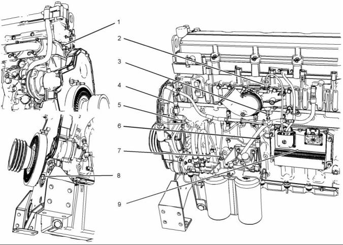
Illustration 17 shows the typical locations of the
sensors on the engine. Specific engines may appear
different from the illustration due to differences in
applications.
This document has been printed from SPI². Not for Resale
![]()
26
SEBU8337
Operation Section
Features and Controls
g01386180
Illustration 17
(1) Engine coolant temperature sensor
(2) Intake manifold pressure sensor
(3) Intake manifold air temperature sensor
(4) Atmospheric pressure sensor
(5) Secondary position sensor (Camshaft)
(6) Engine oil pressure sensor
(7) Fuel temperature sensor
(8) Primary position sensor (Crankshaft)
(9) Electronic control module (ECM)
Failure of Sensors
Programmable Monitoring System
(PMS)
All Sensors
The Programmable Monitoring System determines
the level of action that is taken by the Engine Control
Module (ECM) in response to a condition that can
damage the engine. These conditions are identified
by the ECM from the signals that are produced from
the following sensors.
A failure of any of the sensors may be caused by one
of the following malfunctions:
• Sensor output is open.
• Sensor output is shorted to “- battery” or “+ battery”.
Engine Coolant Temperature
Sensor 1
• Measured reading of the sensor is out of the
specification.
The coolant temperature sensor monitors engine
coolant temperature. The output of the ECM can
indicate a high coolant temperature through a relay
or a lamp. The coolant temperature sensor is used
by the ECM to determine initiation of the Cold Start
Condition.
This document has been printed from SPI². Not for Resale
![]()
![]()
SEBU8337
27
Operation Section
Features and Controls
Failure of the Coolant Temperature
Sensor
Low Oil Pressure Warning
The setpoint for the low pressure warning is
dependent upon the engine speed. The fault will be
active and logged only if the engine has been running
for more than 8 seconds.
The ECM will detect a failure of the coolant
temperature sensor. The diagnostic lamp will
warn the operator about the status of the coolant
temperature sensor. A failure of the coolant
temperature sensor will cause a shutdown of the
engine. The faulty sensor should be replaced. Refer
to Disassembly and Assembly Manual, “Coolant
Temperature Sensor - Remove and Install”.
Low Oil Pressure
The very low oil pressure setpoint is dependent upon
the engine speed. If very low oil pressure is detected,
the ECM will stop the engine immediately unless
Critical Events Override is active.
Intake Manifold Pressure Sensor 2
Failure of the Engine Oil Pressure Sensor
The intake manifold pressure sensor measures boost
pressure in the intake manifold. A signal is sent to the
ECM. A failure of the inlet manifold pressure sensor
will limit the power of the engine.
The ECM will detect failure of the engine oil pressure
sensor. The diagnostic lamp warns the user about the
status of the engine oil pressure sensor. The engine
oil pressure related strategies will be disabled in the
event of a failure of the engine oil pressure sensor.
A failure of the engine oil pressure sensor will cause
a shutdown of the engine. The faulty sensor should
be replaced. Refer to Disassembly and assembly
Manual, “Engine Oil Pressure Sensor - Remove and
Install”.
Intake Manifold Air Temperature
Sensor 3
The Intake manifold air temperature sensor measures
the intake air temperature. A signal is sent to the
ECM. The intake manifold air temperature sensor is
also used by the ECM to determine initiation of the
Cold Start Strategy.
Fuel Temperature Sensor 7
Atmospheric Pressure Sensor 4
The fuel temperature sensor monitors the fuel
temperature. The signal from the sensor allows
the ECM to compensate for changes in the fuel
temperature by adjusting the fuel rate for constant
power.
All the output signals from the pressure sensors are
matched to the output signal of the atmospheric
pressure sensor during calibration. The signal from
the atmospheric pressure sensor is used by the ECM
in order to determine the operating altitude of the
engine. If necessary, the ECM can derate the engine.
Primary Speed/Timing Sensor 8
If the ECM does not receive a signal from the primary
speed/timing sensor , the “DIAGNOSTIC” lamp will
indicate a diagnostic fault code which will be logged
in the ECM memory.
Secondary Speed/Timing Sensor 5
The signal from the secondary speed/timing sensor
is used by the ECM on engine start-up in order to
determine the stroke that the pistons are on. The
secondary speed/timing sensor may be used by the
ECM in order to operate the engine if the primary
speed/timing sensor is faulty.
If the ECM does not receive a signal from the primary
speed/timing sensor (9), the ECM will read the signal
from the secondary speed/timing sensor (2). The
ECM continually checks in order to determine if
there is a signal from both sensors. If either sensor
fails, the faulty sensor should be replaced. Refer to
Disassembly and Assembly Manual, “Crankshaft
Position Sensor - Remove and Install” or refer to
Disassembly and Assembly Manual, “Camshaft
Position Sensor - Remove and Install”.
In order to check the correct operation of the sensor,
refer to Troubleshooting, “Engine speed/Timing
sensor-Test”.
Engine Oil Pressure Sensor 6
Intermittent failure of the sensors will cause erratic
engine control.
The engine oil pressure sensor is an absolute
pressure sensor that measures the engine oil
pressure in the main oil gallery. The engine oil
pressure sensor detects engine oil pressure for
diagnostic purposes. The engine oil pressure sensor
sends a signal to the ECM .
This document has been printed from SPI². Not for Resale
免費(fèi)熱線(xiàn)
400-100-8969???15088860848
400-100-8969???15088860848
機(jī)組銷(xiāo)售
0574-26871589? 15267810868
0574-26871589? 15267810868
配件銷(xiāo)售
0574-26886646? 15706865167
0574-26886646? 15706865167
維修熱線(xiàn)
0574-26871569 18658287286
0574-26871569 18658287286
手機(jī)端

微信公眾號(hào)
在線(xiàn)客服