English
 Espaol
 Franais
 阿拉伯
阿拉伯 中文(簡)
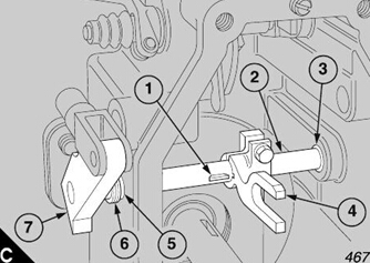
中文(簡) Deutsch
 Italiano
 Português
 日本
日本 韓國
韓國 български
 hrvatski
 esky
esky Dansk
Dansk Nederlands
 suomi
suomi Ελληνικ
 印度
印度 norsk
norsk Polski
 Roman
Roman русский
 Svenska
Perkins3012燃油噴射泵及調(diào)速器的維修保養(yǎng)技術(shù)參數(shù)資料
Perkins3012燃油噴射泵及調(diào)速器的維修保養(yǎng)技術(shù)參數(shù)資料
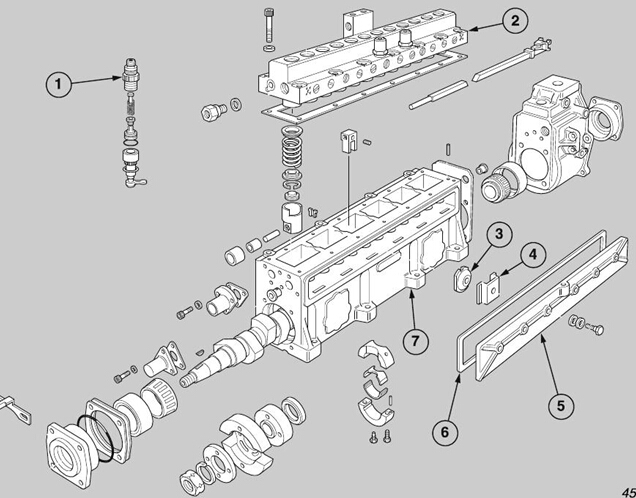
Fuel injection pump and governor
英國帕金斯燃油噴射泵及調(diào)速器
Before the fuel injection pump can be lifted from the
在燃油噴射泵可以從
engine, various other components must be removed.
發(fā)動機(jī),各種其他部件必須拆除。
Obtain a suitable bar, which will fit in the holes in the
獲得一個合適的酒吧,這將適合在洞里
fan belt pulley to turn the c rankshaft when necessary,
風(fēng)扇皮帶輪轉(zhuǎn)動曲軸時必要的,
and proceed as follows:
并進(jìn)行如下:
1 Disconnect and remove the 12 high-pressure fuel
1斷開并拆下12高壓燃油
pipes for the fuel injectors.
燃油噴射管。
2 Disconnect and remove the linkage for the speed
2斷開并拆下速度的連接
control, the linkage for the stop control, and the
控制,停止控制的聯(lián)動
assembly of the engine stop solenoid.
發(fā)動機(jī)停止電磁線圈的裝配。
3 Disconnect and remove the assembly of the levers
3斷開并拆下杠桿的裝配
and the cross shaft.
和十字軸。
4 Disconnect the leak-off pipe from between ’B’ bank
4斷開'乙'銀行之間的泄漏管
and the connection block and the pipes for the spill
和泄漏的連接塊和管道
fuel from the low-pressure relief valves and the gallery
燃油從低壓溢流閥和畫廊
of the fuel injection pump.
燃油噴射泵。
5 Disconnect the low-pressure pipes from the lift
5斷開電梯的低壓管道
pump and the fuel filters.
泵和燃油過濾器。
6 Disconnect the delivery pipe and the drain pipe for
6斷開輸送管和排水管
the lubric ating oil from the cambox and the housing of
潤滑油的流動從三角座和殼體
the governor.
州長。
7 Remove the guard for the assembly of the auxiliary
7拆下輔助裝配的防護(hù)
drive.
驅(qū)動。
8 Turn the engine until the timing marks are aligned.
8轉(zhuǎn)動發(fā)動機(jī),直到計時標(biāo)記對齊。
Remove the two long nuts (A2) from the assembly of
拆下兩長螺母(A2)從總成
the flange (A4) of the auxiliary drive shaft and the
法蘭(A4)的輔助傳動軸和
pack of eight spring steel plates (A3) which are
八彈簧鋼板組(A3),
nearest to the timing case, and withdraw the two bolts
最近的時間的情況下,撤回的兩根螺栓
(A1) of the coupling toward the timing case.
(A1)的耦合對正時箱。
9 Release and remove the eight bolts, the plain
9松開并拆下八個螺栓,平
washers and locking washers, which retain the fuel
保留燃油的墊圈和鎖止墊圈
injection pump.
噴射泵。
10 Connect the lift adaptor, 21825 876, to two of the
holders of the delivery valves. Use a hoist to lift
carefully the fuel injection pump, which is complete
with the governor and the spring steel plates of the
drive coupling, away from the crankcase and on to a
clean bench.
Caution: The clamp ring of the adjustable coupling is
retained securely by special bolts. For early engines,
cap screws are used and for new engines a type of
bolt is used which has a washer integral with the
head.
11 Loosen and remove the four special bolts from the
clamp ring of the adjustable coupling; remove the
clamp ring, and the assembly of the flywheel and the
drive coupling.
12 Use the hoist to lift the assembly of the fuel
injection pump away from the bench. Hold the
assembly over a suitable container, remove the drain
plug from the end face of the governor and tilt the
assembly to allow the lubricating oil to drain from the
cambox and the governor housing.
To fit
Obtain a suitable bar, which will fit in the holes in the
fan belt pulley to turn the crankshaft when necessary,
and fit the fuel injection pump/governor assembly to
the engine as follows:
1 Fit the two off-centre control rods to the speed
control lever and the stop control lever of the
governor.
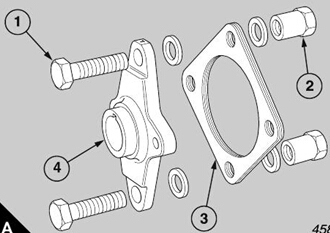
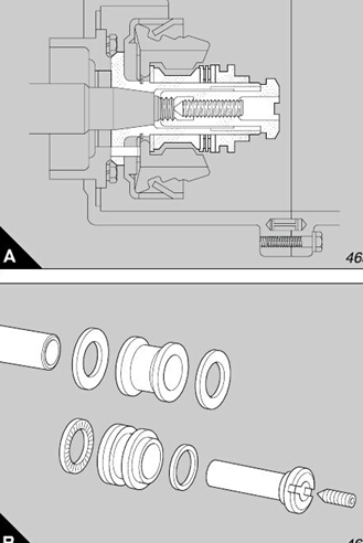
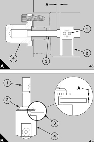
Caution: When the drive coupling for the fuel
injection pump is as sembled, the special plain
washers are fitted only on each side of each pack of
eight spring s teel plates as shown (A). All the nuts are
fitted only on the inner sides of the assembly of the
drive coupling; the four long nuts retain only the drive
shaft for the fuel injection pump.
2 During the assembly of an engine, it is relevant to
assemble first on a bench, the drive shaft for the fuel
injection pump, one pack of eight spring steel plates
and the flywheel, as shown (A). Ensure that the four
bolts, the special plain washers and the nuts are fitted 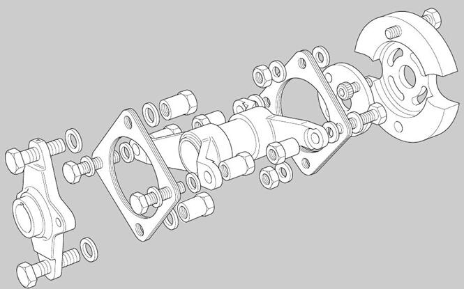
3 Tighten to 120 Nm (88 lbf ft) the two long nuts and
the two standard nuts. Align the assembly with the
hub of the fuel injection pump and fit the clamp ring
with the four special bolts. Insert the special bolts into
the hub until they are finger-tight. Turn the assembly
of the drive coupling until the timing mark on the hub
is aligned with the timing pointer (A).
4 Assemble, on the bench, the flange of the drive
coupling and the second pack of eight spring steel
plates with two bolts, four special washers and two
standard nuts. Use the other two bolts, with four
special washers and two long nuts, to align the other
two holes of each spring steel plate.
5 Ensure that the four bolts, the special washers and
the nuts are fitted correctly, generally as shown (page
167/A). Tighten the two standard nuts to a torque of
120 Nm (88 lbf ft).
6 Check that the taper of the auxiliary drive shaft is
clean, and press the ’Woodruff’ key into its keyway.
Fit the flange for the drive coupling onto the s haft,
followed by the plain washer and the nut. Tighten the
nut to the relevant torque load:
18 mm nut ................. 200 Nm (148 lbf ft).
22 mm nut ................. 300 Nm (220 lbf ft).
7 If necessary, turn the crankshaft until the arm,
which is marked ’T’ (on the flange of the drive
coupling) is above the shaft and is vertical. Remove
the two long nuts from the bolts which pass through
the second pack of eight spring steel plates but retain
the two special washers on the bolts.
8 Use the lift adaptor, 21825 876, and a suitable hoist
to lower carefully the assembly of the fuel injection
pump and the drive coupling into the ’V’ of the
crankcase. Move carefully the assembly toward the
auxiliary drive shaft and enter the protrusions of the
two bolts into their respective holes in the drive shaft
of the fuel injection pump. Ensure that the two special
washers remain on the bolts and fit the long nuts.
Hold the head of each bolt with a ring spanner and
tighten each nut to 120 Nm (88 lbf ft).
9 Insert the eight bolts, with the plain washers, which
retain the fuel injection pump, through the bolt holes
in the base of the fuel injection pump. Tighten each
bolt to 41 Nm (30 lbf ft).
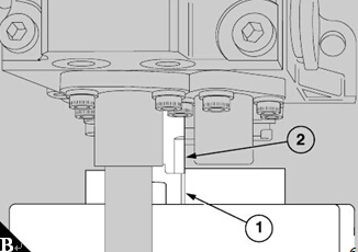
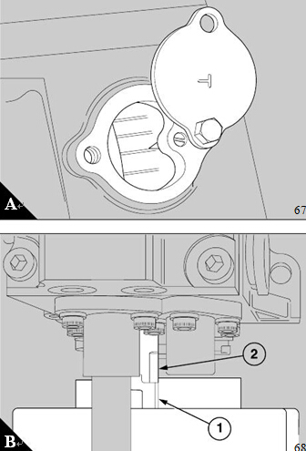
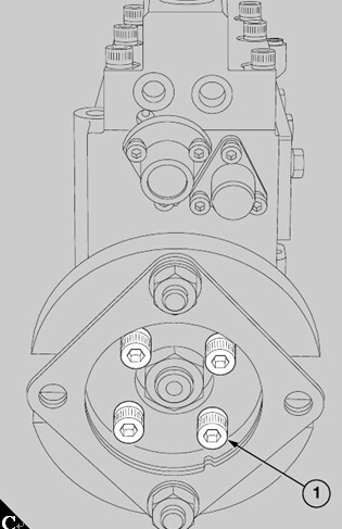
10 Loosen one or two turns the four cap screws (C1)
or, if relevant, the four special bolts in the clamp ring,
and turn the crankshaft until the timing mark on the
flywheel is in alignment with the pointer (A).
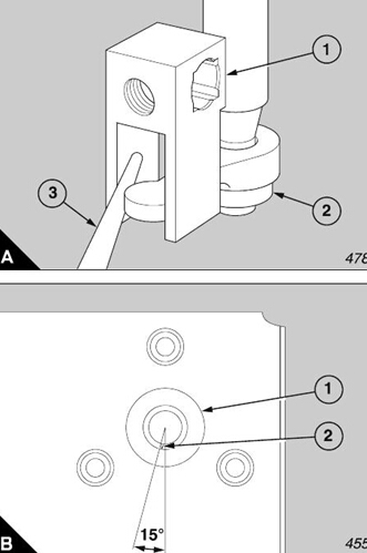
11 Turn the hub of the fuel injection pump by hand in
the normal direction of its rotation (anti-clockwise as
seen from the driven end) until the timing mark on the
hub (B1) passes the timing pointer (B2). Turn slowly
backward the hub until the timing mark and the timing
pointer are correctly aligned. For early engines
tighten the four cap screws (C1) to 69 Nm (51 lbf ft).
For new engines tighten the four special bolts to 46
Nm (34 lbf ft).
Note: The clamp ring of the adjustable coupling is
retained securely by special bolts. For early engines,
cap screws (C1) are used and for new engines a
special bolt is used which has a washer integral with
the head.
12 Turn backward a quarter of a turn (90°) the
crankshaft (anti-clockwise as seen from the front of
the engine). Then turn slowly forward the cranks haft
until the timing marks on the flywheel are aligned
correctly . Check the timing mark of the fuel injection
pump. This, also, should be aligned correctly. If
neces sary, use the same procedure to adjust the
timing again.
13 Ensure that the two 'O' rings are fitted into the
connection on the fuel injection pump which returns
the lubricating oil from the driven end of the cambox.
Slide the pipe on to the connection and engage the
lower end of the pipe in the boss on the cover plate.
Tighten securely the union nut.
14 Fit the guard for the aux iliary drive assembly.
15 Fit the lubricating oil drain pipe between the union
on the servo-valve cover and the boss on the cover
plate in the crankcase ’V’. Inspect the seal in the
cover plate for damage and renew it if necessary. If
the seal is renewed, ensure that the correct type of
seal for your engine is fitted. Apply a small amount of
clean engine oil to the seal, fit the banjo bolt, complete
with a new sealing washer, through the connection at
the top of the pipe and tighten it securely .
Caution: During this operation, hold the banjo
connection to prevent movement of the pipe while the
bolt is tightened. If the pipe moves, it can damage the
seal against its bore in the cover plate.
16 Connect the low-pressure pipes to the lift pump
and the fuel filters.
17 Connect the leak-off pipe to ’B’ bank from the
connection block and the pipes for the spill fuel to the
low-pressure relief valves and the gallery of the fuel
injection pump.
18 Fit and connect the assembly of the levers and the
cross shaft.
19 Fit and connect the linkage for the speed control,
the linkage for the stop control, and the assembly of
the engine stop solenoid. To adjust the linkage of the
stop solenoid refer to operation 23-21.
20 Fit and connect the 12 high-pressure fuel pipes for
the fuel injectors. Tighten the nuts of the high
pressure fuel pipes to 45 Nm (33 lbf ft).
Caution: Ensure that the fuel injection pump is
primed with clean engine oil, of the correct
specification, before the engine is first started.
帕金斯3012柴油泵拆卸和組裝
To dismantle and to assemble
拆卸和組裝
3 Remove the six clips (A4) which retain the
3刪除六剪輯(A4)保留
threaded plates (A3) and turn the threaded plates 90°
螺紋板(A3)和螺紋板90°
to release them from the cambox (A7).
釋放他們從三角座(A7)。
4 Use the spanner OD 5192 to loosen each of the
4用扳手松開的OD 5192
holders of the delivery valves (A1) one or two turns.
對閥門的持有人(A1)的一個或兩個轉(zhuǎn)。
Do not remove the holders during this operation.
請勿在本手術(shù)中移除支架。
5 Release, evenly and gradually, the cap screws
5釋放,均勻地,逐漸地,帽螺絲
which hold together the cambox and the body of the
這抱在一起的三角座的身體
pump (A2). Press lightly downward on the body while
泵(A2)。在身體上輕輕向下按壓
the screws are removed. Do not lift the body of the
螺釘被拆除。不要提起身體的
pump at this stage.
在這個階段的泵。
6 Loosen the vice and put the complete assembly of
6松開副并將其完成裝配
the fuel injection pump and the mounting bracket onto
噴油泵和安裝支架上
the bench.
板凳。
7 Move carefully the assembly of the fuel injection
7小心地移動燃油噴射的裝配
Before the fuel injection pump and the
在噴油泵和
pump onto its side, with the opening downward on the
泵到它的側(cè)面,隨著打開向下的
governor are dismantled, clean thoroughly the
總督被拆除,徹底清除
outside of the assembly with kerosene and dry with
外與用煤油組裝
compressed air.
壓縮空氣。
1 Hold securely the mounting bracket OD 21467 in a
1在一個固定支架上安裝21467個固定支架
vice, fit the assembly onto the bracket and remove the
副,裝配到支架上并拆下
lift adapter, 21825 876.
電梯適配器,876 21825。
2 Remove all locking wire from the assembly, release
2拆下裝配中的所有鎖絲,松開
the six bolts which retain the inspection cover (A5)
六螺栓保留檢查蓋(A5)
and remove the inspection cover and the joint (A6).
并拆下檢查蓋和聯(lián)合(A6)。
bench.
臺。
8 Lift carefully the body of the pump away from the
8小心地抬起泵的身體遠(yuǎn)離
cambox so that the plungers remain in their
三角座使柱塞留在他們
9 Withdraw each plunger c omplete with its spring and
the upper and lower spring plates.
Caution: Put each assembly of a plunger in a
separate container as soon as it has been removed.
Mark each container with the number of the element
to ensure that the components of one element do not
become mixed with the components of another
element.
10 Remove each of the already loosened holders
(A1) of the delivery valves (A5) together with the
spring (A2) and the peg (A6). Place each assembly
in its respective container with its relevant plunger
assembly.
11 Remove and discard the special sealing washers
(A4) from the top of eac h valve guide (A3).
12 Withdraw each delivery valve and its relevant
guide from the body of the pump. Put each as sembly
in its respective container.
13 Use a soft faced hammer on the bottom end of
each barrel (B1) to release it from the body of the
pump. Discard the ’O’ rings (B3) and the was hers
(B2) from the seats of the barrels and put the barrels
in their respective containers.
14 In rotation, dip the plungers and the barrels in
clean test oil and assemble each plunger to its
respec tive barrel to prevent damage to the fine
surface finishes. Return each assembly to its
respectiv e container.
Lift out the assembly of each tappet from the cambox
and dismantle as follows:
15 Push out the pin from the tappet guide and
withdraw the roller and the bush.
16 Remove the circlip from the tappet guide and
withdraw the spacer.
17 Put the assembly of each tappet in its respective
18 Slide out, from between the bores of the tappets,
the ’T’ pieces and make a note of the order of their
removal to ensure that they are assembled correctly.
Hold again the assembly of the fuel injection pump
and the mounting bracket in the vice and proceed as
follows:
19 Release the lock nut and loosen fully the s crew of
the maximum fuel stop which is in the top of the
governor housing (A1). Release the seven bolts
which fas ten the end cover of the governor to the
housing; remove the end c over and the joint.
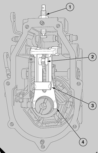
20 Move the end of the variable ramp (A3) upward
and lift out the assembly of the roller for the ramp (A2)
from the control fork (B2) of the speed control.
21 Make a note of the arrangement of the primary
spring (A4) and the variable ramp, to ensure that they
will be assembled correctly, and withdraw the pivot
from the s ide which is opposite to the inspection cover
of the cambox. Remove the primary spring and the
variable ramp.
22 Remove the bolts and the spring washers from the
flange of the pivot and remove the ’E’ type circlip from
the inner end of the pin; remove the shim washer from
behind the circlip.
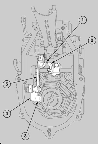
23 Hold the lever of the servo-valve (B4), the shims
and the assembly of the connection type lever (B5)
and withdraw the pivot with the joint. Remove the
shims.
24 Move both levers to the left and forward to release
the slipper pin (B3) from the groove in the thrust plate,
which is a component in the assembly of the governor
hub. Withdraw the slipper pin and separate the two
levers.
25 Remove the two extension type springs (B1) from
the control rod and the connection ty pe lever. Lift out
the connection type lever.
26 Use a suitable tool to hold the hub of the fuel
injection pump, and loosen the locking screw in the
centre of the nut on the hub of the governor.
27 Use the key OD 21465 to release and remove the
nut of the hub, together with the spacers.
28 Use the extractor OD 21466 to withdraw the
complete hub of the governor (A) from the taper on
the end of the camshaft; separate the components
(B).
29 Use a sharp device to remove the ’Spirolox’ ring
from its groove in the governor hub, and lift away the
plate type retainer and the governor weight holder.
Press out the six rubber blocks from the slots in the
governor weight holder.
Make a note of the position of the speed control lever,
relative to the control fork for the roller, to give
assistance when the unit is assembled and proceed
as follows:
30 Loosen the clamp setscrews and withdraw the
speed control lever (C7), which has an integral stop
on new engines. Remove also the separate stop of
early engines.
31 Loosen the clamp setscrew on the control fork for
the roller (C4) and slide the control fork for the roller
along the shaft (C2) to enable the ’Woodruff’ key (C1)
to be removed.
32 Remove the ’E’ type c irclip, the plain washer, the
special spring washer (C6) and the inner plain washer
(C5) from the speed control shaft at the end for the
lever. Withdraw the shaft and lift out the control fork
for the roller.
33 Remove and discard the ’O’ ring type seals, and
the retainer rings, from the bushes (C3) of the speed
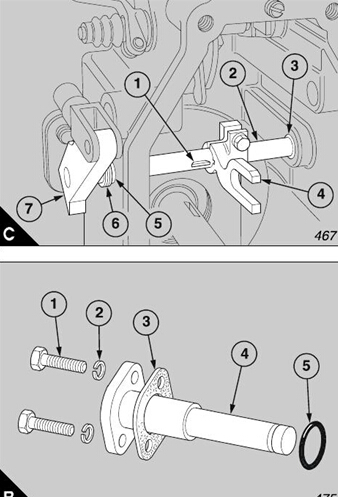
34 Remove the ’Groverlok’ pin (A7) which secures
“‘groverlok引腳34刪除,secures(A7)
the assembly of the lever for ’maximum stop’ (A3) to
該組件的最大杠桿是停止(A3)
the shaft of the excess fuel device (A4). Remove the
過量的燃料裝置的軸(A4號)。刪除的
rubber shroud from around the excess fuel button
橡膠罩來自過剩的燃料。
(A10) and remove also the stop control lever (A1).
(10)和刪除的控制桿也停止了(A1)。
35 Release the cap (A6) at the opposite end of the
釋放帽(35)是在對面的盡頭)
shaft and remove the spring and the washer.
軸、彈簧和墊圈刪除。
36 Remove the retainer ring, the washer and the ’O’
刪除的36型聘環(huán),墊圈和“O”的
ring type seal from around the excess fuel button,
型密封環(huán)的過量燃料來自巴頓
slide out the shaft for the excess fuel and remove the
該軸滑出的燃料和消除過剩的
retainer ring, the assembly of the lever for ’maximum
型聘環(huán),是最大的杠桿總成
stop’, the sealing washer (A8), the assembly of the
停止,密封墊圈(A8)的,該組件
shaft for the stop control (A9), the thrust washer (A2)
軸的停止控制(A9),(A2)的推力墊圈
and the bush (A5).
和布什(5)。
To inspect the servo-valve and the assembly of the
在對伺服閥和inspect匯編的
piston, the cover of the valve must be removed from
活塞的閥蓋,必須刪除從
the end cover of the governor. According to which
端蓋的州長。根據(jù)這
type of end cover is fitted, proceed as follows:
端蓋是一種基于í,如下:
37 If the early type of end cover is fitted, remove the
37,如果類型是基于早期的端蓋,清除
vent plug, and the connection of the inlet for the oil,
通風(fēng)插頭和連接的入口的油
from the cover of the servo-valve. Remove the cover
從覆蓋的伺服閥。該蓋去除
of the servo-valve, discard the joint, and remove and
的伺服閥,聯(lián)合和刪除和丟棄。
discard the ’O’ ring type seal from the groove in the
丟棄的O型圈密封在從槽型
cover of the servo-valve. Lift out the assembly of the
蓋的伺服閥。大會的升降機(jī)-PSP
servo-valve.
伺服閥。
38 If an altered type of cover is fitted for the servo-
如果一個覆蓋38是基于蝕變類型的伺服
valve, remove the vent plug and the connection of the
在排氣閥,刪除和連接的插頭
inlet for the oil and push upward the assembly of the
進(jìn)口的石油和upward匯編的《推
piston to remove the plug which is fitted below the
活塞,這是消除基于下面的插頭
flange of the cover. Discard the ’O’ ring type seal and
法蘭的封面。丟棄的O型圈密封型和
the joint of the cover.
該接頭的蓋。
39 If the new type of end cover for the governor is
如果新的39型端蓋是在州長
fitted (page 153/A), remove the circlip which retains
基于(153頁),《circlip retains移除它
the plug in the top of the bore, withdraw the plug and
《頂級孔插頭,插頭和退休
remove the ’O’ ring type seal. Remove the circlip
刪除的O型圈密封型。刪除的circlip
which retains the internal plug in the bore of the piston
這retains插頭內(nèi)孔的活塞
and push up the servo-valve and piston assembly to
推上的伺服閥門和活塞組件。
remove the plug. Discard the ’O’ ring type seal.
插頭刪除。丟棄型的O型圈密封。
After the governor has been dismantled, continue to
州長已經(jīng)dismantled后,繼續(xù)
dis mantle the fuel injection pump. Proceed as
在燃油噴射泵的DIS的地幔。í的
40 Remove the three cap screws and the spring
washers which retain the cover for the control rod to
To assemble
20
the cambox. Remove the cover and the joint.
41 Loosen each of the cap screws which fasten the
control forks to the control rod and slide the control
rod out through the governor housing. Lift out the
control forks as they become free.
42 Fit the anti-rotation tool OD 21468 on the hub at
the drive end of the fuel injection pump and use the
key OD 21465 to release the lock nut which retains
the hub. Use the puller OD 5343 to withdraw the hub
from the taper of the camshaft, and remove the
’Woodruff’ key.
43 Loosen the lock nuts and remove from under the
cambox the screws which retain the two inner
bearings.
44 Remove the four ’Tuflok’ bolts, and the four bolts
with spring washers, which retain the housings of the
front and rear roller bearings to the cambox. Remove
the timing indicator.
45 Use a soft faced hammer to hit lightly the rear end
of the camshaft and loosen the bearing housing from
the front end of the cambox. Withdraw the bearing
housing and remove the shims ; discard the oil s eal
and the ’O’ ring type seal. Hit lightly the front end of
the camshaft to loosen the rear bearing housing and
withdraw the camshaft, with the two assemblies of the
inner bearings, from the cambox
46 Remove the two bolts which retain each of the two
bearing caps, and separate the bearing caps and the
half bearings from the camshaft.
Caution: Each bearing cap is stamped with a
number to ensure its correct relationship when it is
assembled.
47 Use suitable extractors to remov e the inner races
of the bearings from each end of the camshaft and to
withdraw the outer races from the front and the rear
bearing housings. Keep together each inner race and
its relevant outer race as an assembly and put in to
storage.
48 If it is necessary to separate the governor housing
from the cambox, remove from inside the housing the
one bolt which remains. Disc ard the joint.
1 Put a new joint on the cambox face at the end for
the governor. Ensure that the ports which circulate
the oil are not restricted and use the central ’Tuflok’
bolt to c onnect the governor housing to the cambox.
2 Use a hollow drift to fit the inner races of the
bearings to each end of the camshaft.
3 Lubricate lightly the outer races of the bearings and
press them into their respective bearing housings.
4 Fit the rear bearing hous ing to the gov ernor
housing, apply a small amount of Loctite 241 to the
threads of the four bolts which retain the housing and
fit the bolts, with new spring washers, into the bolt
holes. Tighten each bolt to 25,75 Nm (19 lbf ft).
Tighten the ’Tuflok’ bolt to 16 to 20 Nm (12 to 15 lbf ft).
5 Remove the assembly of the cambox from the vice
and put it in an upright position on the governor
housing. Lower carefully the assembly of the
camshaft into its position in the cambox, fit the shims
to the drive end of the cambox and fit temporarily the
bearing housing. Fit the four ’Tuflok’ bolts and tighten
them to 16 to 20 Nm (12 to 15 lbf ft). Fit again the
assembly to the vice.
6 Use a dial test indicator with a magnetic base to
check the end float of the camshaft. The permissible
end float is 0,05 to 0,127 mm (0.002 to 0.005 in). If
necessary, vary the thickness of the shims to adjust
the end float.
The shims which are av ailable for this purpose are
listed below:
Part No. Shim thickness
509582 0,19 mm (0.0076 in)
509583 0,27 mm (0.0108 in)
509584 0,38 mm (0.0148 in)
7 Loosen the four ’Tuflok’ bolts and put the assembly
in an upright position on the governor housing.
Remove the bolts, the bearing housing and the shims.
Withdraw the camshaft.
8 Apply clean engine lubricating oil to the central half
bearings. Fit the as sembly of each bearing onto the
camshaft and ensure that the marks which give the
correct relationship are aligned correctly. Fit the
dowels and the bolts, and tighten the bolts to 6 to 7,5
Nm (4.5 to 5.5 lbf ft).
9 Fit the assembly of the camshaft into the cambox
and align the two inner bearings with the threaded
holes in the base of the cambox. To prevent the
leakage of the lubricating oil from the cambox, apply
’Loctite 242’ to the threads of the two screws which
retain the two inner bearings. Fit the screws, with
their lock nuts, through the base of the cambox, into
the bearing caps. Tighten by hand until the spigot of
each screw is engaged fully in its bearing cap.
Loosen each screw half a turn and tighten the lock
nuts to 16 to 20 Nm (12 to 15 lbf ft). Ensure that the
screws do not turn when they are tightened.
Hold the assembly of the c ambox in the vice and
proceed as follows :
10 Press a new oil seal into the bearing housing with
the lip of the seal toward the centre of the fuel
injection pump. Put the necessary shims over the
spigot of the housing, s pread a small amount of
silicone grease around the spigot and fit a new ’O’ ring
into the groove.
11 Fit the bearing housing to the cambox, align the
bolt holes and fit the four ’Tuflok’ bolts and the timing
indicator. Tighten gradually and evenly the bolts to 16
to 20 Nm (12 to 15 lbf ft).
12 Fit the ’Woodruff’ key into the keyway, slide the
hub onto the taper of the camshaft and fit the spring
washer and nut. Use a suitable tool to hold the hub of
the fuel injection pump and tighten the nut to 150 Nm
(110 lbf ft).
Ensure that all the components of the pump body
have been cleaned thoroughly and proceed as
follows:
13 Dip each component in clean test oil. If they have
been removed, fit the plugs and new sealing washers
at the ends of the gallery. Tighten each plug to 115 to
136 Nm (85 to 100 lbf ft).
14 If the blanking plugs along the gallery have been
removed, dry the threads, apply ’Loctite 241’ to the
thread of each blanking plug, fit new sealing washers
and insert the blanking plugs into the body of the
pump. Tighten each blanking plug to 32,5 to 40,5 Nm
(24 to 30 lbf ft).
15 Fasten temporarily the body of the pump to the
cambox and fit new washers for the seats of the
barrels into each bore in the body. Align the
serrations of each barrel with those in the body and
assemble it to its correct location.
16 Apply some silicone grease to the new ’O’ rings
(page 172/B3) and put one on the top of each barrel.
For each element in rotation, fit the guide for the
delivery valve, the delivery valve and a new special
sealing washer.
17 Fit the springs of the delivery valves, followed by
the pegs which reduce the volume.
18 Apply ’Castrol grease 5903’ to the threads of the
holders of the delivery valves and fit eac h holder into
its respective location. Use the soc ket type spanner
OD 5192 to tighten each holder to 115 to 129 Nm (85
to 95 lbf ft). Remove the assembly of the pump body
from the cambox.
19 Slide the control rod through the bush at the rear
end into the cambox and, at the same time, fit the
control forks onto the rod in the correct s equence.
20 Put the control fork (A2) for no.1 element 3,0 mm
(0.118 in) from the end (dimension A) of the square
section of the rod (A3) and tighten its locking screw
(A1) to 4,75 to 6,0 Nm (3.5 to 4.5 lbf ft).
21 Slide backward the control rod by a small amount
to align the no.1 control fork with the centre of the
bore of its tappet. Align the remainder of the 11
control forks with the bores of their respective tappets
and tighten the locking screws as instructed for no.1
control fork.
22 Fit the end cover (A4) for the control rod. Use a
new gasket and new spring washers and tighten the
three cap screws to 2,70 to 4,0 Nm (2 to 3 lbf ft).
Check that the control rod slides freely in its bushes.
23 Assemble the roller of the tappet, the bush and the
pin into each tappet guide. Insert the tappet spacer
and fit the circlip, with the c onvex side next to the
spacer, to retain the assembly.
24 Check the clearance, dimension ’A’ as shown (B),
between the arm of each plunger (B3) and its
respec tiv e tappet spacer, as given below:
25 Assemble the lower spring plate (B2) to the
plunger (B1) and hold firmly the seat of the lower
spring plate in its position in the body of its relevant
tappet. Use the feeler gauges to check the clearance
between the bottom face of the lower s pring plate and
the shoulder on the arm of the plunger. The
permis sible clearance is from 0,05 to 0,20 mm (0.002
to 0.008 in). If the clearance exceeds these limits, the
lower spring plate must be ex changed for a lower
spring plate with a suitable thickness. Refer to the
end of this section.
Move the mounting bracket of the fuel injection pump
in the vice until the camshaft has an approximately
20° angle of tilt, with the drive end of the camshaft at
the lower position, then proceed as follows:
26 Insert no.1 tappet into its bore in the cambox with
the cut-out in the tappet body toward the control fork.
Fit carefully the ’T’ piece to its position next to the
tappet. The ’T’ piece will be against the s ide of the
tappet, which will reduce the danger that it may fall
into the cambox. Fit the remainder of the tappets and
the ’T’ pieces in the correct sequence.
27 When all the tappets have been fitted into the
cambox, remove the assembly of the fuel injection
pump from the vice and put it on its side with the
opening downward on the bench to enable the body
of the pump to be fitted. Align the control forks with
the assemblies of their respectiv e tappets.
28 Insert the pump plungers into their respective
barrels and fit a lock plate to the pump body to retain
the plungers . Connect a supply of compressed air to
the inlet connection for fuel and close all other
openings in the fuel gallery with temporary blanking
plugs.
29 Check for leakage of air by the complete
immersion of the pump body in a container of c lean
test oil. Ensure that the air pressure does not exceed
345 kN/m (50 lbf/in ) and allow the air to enter the
gallery. Check for the formation of air bubbles. A
small amount of leakage from around the plungers is
acceptable but further leakage must be corrected
before the procedure can continue.
30 When the pressure test is completed, and is
acceptable, remove the assembly from the container
of oil, disconnect the supply of air and remove the
temporary blanking plugs. Allow the surplus oil to
drain from the pump body.
31 Put the pump body on its side with the inlet
connection for fuel at the top. Fit the lower spring
plate to each plunger, the spring which returns the
plunger and the upper spring plate. Insert the
plungers into their respective barrels, with the arms of
the plungers vertically downward.
32 Put a new joint on the top face of the cambox and
fit carefully the pump body . Ensure that the arms of
the plungers engage correctly in their control forks.
Insert four cap screws, with new sealing washers, into
the bolt holes at the corners of the pump body and
tighten securely the cap screws.
|
to a ’Hartridge HA 3000’ test rig, or a similar test rig,
and connect a supply of low-pressure oil to the
adaptor in the inlet of the pump body. Ensure that the
oil pressure does NOT exceed 14 kN/m (2 lbf/in ).
Do not start the flow of the oil at this stage.
34 Remove the holder of the delivery valve, the peg
which reduces the volume, the spring of the delivery
valve and the delivery valve from the no.1 element of
the pump.
35 Use the adaptor 89558/10 and the holder ST 184
to fit the dial test indicator 23764, in the place of the
holder of no.1 delivery valve.
36 Slide the control rod for the fuel to the position of
’maximum fuel’, that is, toward the governor, and turn
the camshaft until the no.1 plunger is at the bottom of
its stroke, that is, with the tappet roller on the back of
the cam.
37 Start the flow of oil to the pump body and check
the flow of oil from the base of the gauge holder. Turn
slowly the camshaft in its normal direction of rotation
until the flow of oil stops; this is known as the point of
’spill cut-off’ and it is also the point at which the no.1
element starts to inject the fuel during the operation of
the engine. Check the timing mark on the hub of the
camshaft, the front edge of the mark should be
aligned with the edge of the indicator plate. If the
point of spill cut-off has been correctly obtained and
the edges are not aligned, a new timing mark should
be made on the hub of the camshaft to align with the
indicator plate.
38 Check the reading on the dial test indicator and
measure the movement of the plunger from the
bottom of its stroke to the point of spill cut-off.
Compare this reading with the correct stroke given in
the test schedule.
39 To adjust the length of the stroke, remove the
assembly of the pump from the test rig and release
the four cap screws which retain the body. Put the
assembly on its side with the opening downward and
withdraw carefully the body of the pump and the
assemblies of the plungers.
40 Withdraw and dismantle the assembly of the no.1
tappet and exchange the spacer for another spacer of
the necessary thickness to give the correct movement
of the plunger.
Caution: Ensure that the original clearance is
maintained between the spacer and the lower s pring
plate. If a thicker spacer is fitted to the assembly of
the tappet, a lower spring plate, which is respectively
thinner, must be fitted. When a thinner spacer is
necessary, a lower spring plate, which is respectively
thicker, must be fitted. A list of the sizes of the
spacers and the spring plates is given at the end of
this section.
41 Fit the pump body to the cambox as already
instructed (see paragraph 32) and install the pump on
the test rig. Check again the movement of the no.1
plunger and, if it is correct, set to zero the degree
plate on the test rig. This setting will give a datum to
check the remainder of the elements.
42 Stop the flow of oil and remove the dial test
indicator, the holder and the adaptor from the no.1
element. Fit again the assembly of the delivery valve.
Use the socket type spanner OD 5192 to tighten the
holder of the delivery valve to 115 to 129 Nm (85 to 95
lbf ft).
43 Remove the components of the delivery valve
from the next element in the injection sequence,
which is no.9 element, and connect a swan neck pipe
to the holder of the delivery valve as shown (A). Start
the flow of oil.
|
rotation and check the flow of oil from the swan neck
pipe. When the plunger begins to close the inlet port,
the flow of oil will gradually decrease. Continue to turn
very slowly the camshaft until the flow of oil stops
completely. Check the reading on the degree plate.
If the point of spill cut-off is correct, the degree plate
should indicate 30°. If the reading on the degree plate
is not within 30°± /2°, make a note of the reading to
ensure that the spacer of the tappet can be changed
later. Stop the flow of oil, remove the swan neck pipe
and assemble the components of the delivery valve.
Apply the correct torque to tighten the holder of the
delivery valve.
45 Repeat the procedure for each of the remainder of
the elements, in increments of 30°. Follow the
sequence given below.
Sequence 1 9 4 11 2 7
Degrees 30 60 90 120 150 180
Sequence 6 10 3 8 512
Degrees 210 240 270 300 330 360
46 Disconnect the supply of oil and remove the pump
from the test rig. If the timings for the injec tions of one
or more of the elements of the pump were incorrect,
exchange the spacers and the lower spring plates for
those of the correct thickness, and check again the
pump on the test rig.
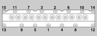
47 Hold in the vice the pump assembly on its
mounting plate and loosen the four cap screws. Insert
the remainder (11) of the cap sc rews, with new
sealing washers, and tighten each cap screw, evenly
and gradually, in the sequence shown (A) to a torque
of 20,3 to 20,4 Nm (15 to 17 lbf ft).
48 Check that all the lower spring plates are fitted
correctly on their tappet as semblies and that the
control rod moves freely.
49 Before the governor is assembled, chec k all the
components for wear or damage, especially the thrust
faces and the bearing surfaces; renew components or
assemblies where necessary.
50 Check the tension of the spring in the servo-valve
assembly and, if necessary, renew it. Dip the
assembly in clean test oil and slide it into the s ervo-
valve piston. Fit the piston into the bore in the cover
of the governor and align the slot in the piston to
receive its guide sc rew.
51 Apply silicone grease to a new ’O’ ring type seal
and fit it into its groove in the servo cover. Assemble
the cover to the bore of the piston as shown (A). If
relevant to the type of cover, fit new joints and sealing
washers. Tighten the vent plug and the inlet
connection for oil to a torque of 27,0 to 34,0 Nm (20.0
to 25.0 lbf ft).
52 Fit a new retainer ring and two new ’O’ ring type
seals to the excess fuel shaft (B4). Lubricate the
shaft, and the bore of the stop control shaft (B9), with
’Rocol ASP’ molybdenum disulphide grease. Slide
the excess fuel shaft through the wall in the side of the
governor housing, with the flat surface face
downward.
53 Fit the thrust washer (B2), the assembly of the
stop control shaft, the sealing washer (B8), the
assembly of the ’maximum stop’ lever (B3) and the
bush (B5) on to the excess fuel shaft. Continue to
slide the shaft through the governor housing and put
the bush in the bore of the housing.
54 Apply ’Loctite 241’ to the thread of the bush, fit a
new washer around the thread of the bush and insert
the spring in the cap. Fit the cap (B6) onto the bush
and tighten the cap to a torque of 20 to 23 Nm (15 to
17 lbf ft).
55 Push the excess fuel shaft fully into its location
and press the ’Groverlok’ pin (B7) into the assembly
of the ’maximum stop’ lever. Fit the stop control lever
(B1) and tighten the bolt which retains the lever to a
torque of 4,5 to 5,5 Nm (3.5 to 4.0 lbf ft). Fit the rubber
shroud over the end of the shaft (B10).
56 Insert two rubber pads into each slot in the base
of the governor weight holder. Put the hub of the
governor on the bench and fit carefully the weight
holder over the hub so that the rubber pads are on
each side of the three drive pegs. Ensure that there
is no distortion of the pads and that they are not
damaged during this operation.
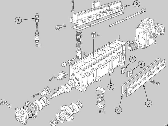
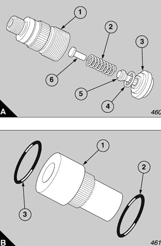
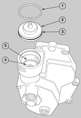
Key to illustration A
1 Circlip
2 Servo-valve cover
3 ’O’ ring
4 Servo-valve guide
5 Circlip
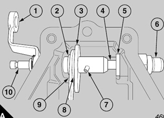
57 Put the plate type retainer over the protrusions of
the pegs and fit the ’Spirolox’ ring into its groove in the
hub body (A1).
58 Fit the six weights into the weight holder of the
governor. Put the 48,3 mm diameter thrust washer
(A2) against the thrust faces of the weights, and the
bobbin type sleeve (A3) against the thrust washer.
59 In sequence, fit the thrust washer(s) (A4), the
needle type thrust bearing (A8), the thrust plate (A7)
and the spacer(s) (A6) onto the hub of the governor
and put the hub assembly on the tapered end of the
camshaft.
60 Hold the camshaft hub with the tool OD 21468 and
fit the nut. Use the tool OD 21465 to tighten the nut to
a torque of 38,0 to 43,5 Nm (28 to 32 lbf ft).
Check that the joint fac e of the governor housing is
clean, ensure that the governor weights are in the
’fully closed’ position and proceed as follows:
61 Use a depth gauge to measure accurately the
distance ’Y’ from the joint face of the housing to the
face of the outer flange of the thrust plate (B). See the
test schedule of the fuel injection pump to chec k the
measurement. If the reading on the depth gauge is
incorrect, the thrust washer(s) may be exchanged for
new washers of the necessary thickness.
62 Apply ’Loctite 241’ to the threads of the locking
screw and fit it into the threaded bore of the hub nut.
Tighten the locking screw to a torque of 20 to 27 Nm
(15 to 20 lbf ft).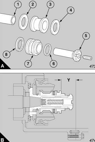
63 Press the ’E’ type circlip (A6) into its groove in the
speed control shaft, at the lever end. Fit the outer
washer, the special spring washer and the inner
washer (A5) against the inner face of the ’E’ type
circlip. Fit new retainer rings and new ’O’ ring type
seals into the bushes (A3) which support the shaft
(A2) in the governor housing. Lubricate the bushes
with silicone grease and slide the shaft into the
housing from the side for the lever. Fit the control fork
for the roller (A4) onto the shaft and insert the shaft
through the second bush in the opposite side of the
housing. Fit the plain washer, the special spring
washer and the second ’E’ type circlip to the
protrusion of the shaft.
64 Slide the speed control lever (A7) on to the splined
end of the shaft and tighten the bolt which retains the
lever to a torque of 4,5 to 5,5 Nm (3.5 to 4.0 lbf ft).
65 Press the ’Woodruff’ key (A1) for the control fork
into the shaft and slide the control fork into its location
over the key. The central line through the control fork
must be within 0,25 mm (0.010 in) of the vertic al
central line of the governor housing. When the lever is
positioned correctly, tighten the bolt which retains the
lever to a torque of 4,5 to 5,5 Nm (3.5 to 4.0 lbf ft).
66 Use a small wire hook to connect the two springs
(C2) to the control rod.
67 Fit a new ’O’ ring type seal (B5) and a new joint
(B3) on the pivot ((B4). Ins ert partially the pivot into
the governor housing and fit the thrust washers over
the protrusion of the inner end of the pivot.
68 Fit the slipper pin (C4) into the lever of the servo-
valve and assemble the connection type lever to the
lever of the servo-valve, with the dowel in its correct
location. Fit both levers in the housing, with the
slipper pin engaged in the groove in the thrus t plate
(C3). Press the pivot through the bores of the two
levers, and fit the shim washer and the ’E’ type circlip
over the protrusion of the end of the pivot. Fit the two
bolts (B1), with new spring washers (B2) through the
flange of the pivot and tighten them to a torque of 4,0
to 7,0 Nm (3 to 5 lbf ft). Connect the free ends of the
two springs to the assembly of the connection type
69 Fit a new ’O’ ring type seal to the pivot for the
spring of the governor. Assemble the leaf spring and
the variable ramp in the governor housing. Insert the
pivot into its bore in the side of the housing for the
control lever and through the eyes of the assembly of
the leaf spring and the ramp. Push the pivot fully into
its correct location until the ends are aligned precisely
with the faces of the governor housing.
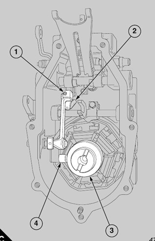
At this stage of the operation, set the control rod of the
fuel injection pump as follows:
70 Remove the three cap screws which retain the
end cover of the control rod to the cambox. Remove
the cover and the gasket.
71 Loosen the adjustment screw (page 184/C1) in
the top of the connection type lev er of the governor.
Hold the weights of the governor in the ’fully open’
position and turn the adjustment screw until the
square section of the control rod for fuel is just in
contact with the face of the bush at the drive end of
the cambox.
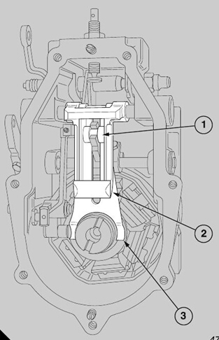
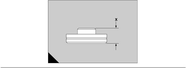
72 Measure accurately the protrusion of the round
section of the control rod from the outer face of the
cambox, (A, dimension X) and make a note of the
measurement. Turn anti-clockwise the adjustment
screw to reduce the measurement by 0,1 to 0,5 mm
(0.004 to 0.020 in) (A, dimension Y). Tighten
temporarily the lock nut of the adjustment screw and
check again the protrusion. If the protrusion is
correct, tighten fully the lock nut.
73 Hold the weights of the governor in the ’fully
closed’ position, press the excess fuel device and
check the movement of the control rod. The
movement must not be less than 24 mm (0.94 in).
74 Fit the joint and the end cover for the control rod
and tighten the cap screws to a torque of 2,70 to 4,0
Nm (2.0 to 3.0 lbf ft).
When the movement of the control rod is set correctly,
continue to assemble the governor as follows:
75 Put the convex bottom end of the primary spring
(B3) against the face of the thrust plate and turn the
end of the variable ramp (B2) upward. Put the
assembly of the roller for the ramp (B1) in the fork of
the control lever, with the large diameter of the roller
against the outer face of the primary spring, and lower
the variable ramp.
76 Apply grease to both sides of a new joint for the
cover and put the joint on the housing. Remove the
large plug from the end cover of the governor and fit
carefully the cover to the housing. Ensure that the
connection type lever and the lever for the servo-
valve are engaged correctly in the recesses in the
piston of the servo-valve and in the servo-valve. Fit
the seven bolts, with new spring washers, which
retain the end c over and tighten each bolt to a torque
of 5,5 to 8,0 Nm (4.0 to 6.0 lbf ft).
Caution: Before the large plug is fitted, check again
that the assembly of the lev ers is engaged correctly in
the servo-valve and its piston and that all the moving
parts of the governor have a full and free range of
movement. A failure to do these checks could cause
the engine to be badly damaged by excessive speed.
77 Fit the large plug, with a new joint, and tighten it to
a torque of 38,0 to 41,0 Nm (28.0 to 30.0 lbf ft). Use
locking wire to ensure that the plug is retained
清洗燃油噴射泵的所有部件
clean test oil and dry them with compressed air.
清潔試驗油,并用壓縮空氣干燥。
Check each part for wear and damage in accordance
檢查各部分的磨損和損壞情況
with the instructions given below:
下面給出的說明:
1 Inspect the plunger and the barrel for marks or
1檢查活塞和桶的痕跡或
damage. Very small scratches are acceptable but
損傷。非常小的劃痕是可以接受的,但
deep scratches, and roughness on the upper edge of
深的劃痕,和粗糙度的上邊緣
the groove for spill fuel, indicate excessive wear. In
泄漏燃料的槽,表明過度磨損。在
this situation, it is recommended that all the elements
這種情況,建議所有的元素
of the fuel injection pump are renewed.
燃油噴射泵的更新。
2 If the components have very small scratches,
2如果組件有很小的劃痕,
assemble each element in clean test oil. Hold
組裝各單元在清潔測試油。持有
vertically the assembly and turn the plunger in both
垂直的組件,并把柱塞在這兩個
directions . The assembly is acceptable if the plunger
方向。該組件是可以接受的,如果柱塞
rotates freely without interference and if, when the
自由旋轉(zhuǎn)而不受干擾,當(dāng)
plunger is released, its weight causes it to fall slowly.
柱塞被釋放,它的重量使它慢慢地下降。
3 Inspect the spring, which returns the plunger, for
3檢查彈簧,該彈簧返回柱塞,用于
cracks and corrosion and check the length of the
裂紋和腐蝕,檢查長度
spring against a new spring. If it is defective, fit a new
春天對一個新的春天。如果是有缺陷的,適合一個新的
set of springs.
彈簧組。
4 Check the seats of the barrels in the pump for
4檢查泵中的桶的位置
erosion or other damage. If necessary, correct the
侵蝕或其他損壞。如果需要,正確
seats with the tool ST 146. Remove only the
座位與工具146。只刪除
minimum amount of metal to res tore the faces of the
金屬的最小量的撕裂的臉的
seats.
座位。
5 Check the assemblies of the delivery valve for
5檢查閥門的總成
erosion and deposits which may be caused by the
可能引起的侵蝕和沉積
contamination of the fuel oil; renew the assemblies if
燃油的污染;如果更換組件,如果
necessary.
必要的。
6 Check the camshaft for damage or erosion.
6檢查凸輪軸的損壞或侵蝕。
Excessive wear on the cams will affect the
凸輪上的過度磨損會影響到
characteristics of the injection of the fuel.
燃料的注入特性。
7 Check the camshaft bearings for wear or signs that
7檢查凸輪軸軸承的磨損或標(biāo)志
they have been affected by excessive temperature.
他們受到過多的溫度影響。
Check that the races of the bearings are not worn and
檢查軸承的種族不磨損和
that there is no erosion. If there are signs of wear or
有沒有侵蝕。如果有磨損的跡象或
8 Inspect the walls of the tappets for wear, and check
the bores of the cambox, especially around the ’T’
pieces. Renew all worn components.
9 Check the assemblies of the rollers for wear. If
necessary, renew the rollers, the pins and the bushes.
10 Use the relevant feeler gauges (A3) to check the
clearance between each control fork (A1) and the arm
of its respective plunger (A2). The permissible limits
are 0,01 to 0,20 mm (0.0004 to 0.008 in). If a gap is
excessive, renew the element and/or the relevant
control fork.
11 Fit temporarily a new control rod to check the
bushes of the control rod for wear and ovality. If the
clearance is excessive, withdraw the control rod, drive
the locking pin into the rear bush and carefully remove
both bushes.
12 Fit a new bush for the rear end, ensure that the
holes for the locking pin in the cambox and the bush
are aligned correctly, then insert the locking pin into
its position through the top face of the cambox.
Ensure that the pin is engaged in the bush but does
not extend into the bore of the bush.
13 Press in a new bush (B1) at the front end. Ensure
that the ’V’ groove (B2) on the front face of the bush
is 15 degrees to either side of B.D.C.
14 Check that the control rod moves freely in the new
bushes and then withdraw the rod.
英國帕金斯柴油發(fā)動機(jī)噴油泵校準(zhǔn)
1 The accurate measurement and adjustment of the
fuel, which is supplied by each element of the pump,
can be done only with the use of special equipment
and by the personnel who have had the correct
training. Unless the equipment and the personnel are
available, the fuel injection pump must be returned to
the manufacturer.
2 Fit the assembly of the fuel injection pump onto the
test rig and ensure that there is a minimum clearance
of 0,5 mm (0.02 in) between the fuel injection pump
and the coupling of the test rig.
3 Connect the delivery pipe, for the lubricating oil,
and the drain pipe to the fuel injection pump and the
governor. Connect the delivery pipe for the test oil to
the gallery of the fuel injection pump. Connect the
drain pipes to the outlets of the low-pressure relief
valves.
4 Start the flow of test oil and loosen the unions at the
relief valves. When the leakage of oil is shown to be
free from bubbles, tighten securely the unions.
5 Check the distance (dimension ’A’) between the
end face of the fork (A2) for no.1 element and the
square shoulder of the control rod (A3). If necessary,
loosen the locking screw (A1) which retains the
control fork and slide the control fork along the rod to
give a reading of 0,30 mm (0.012 in) at dimension ’A’.
Tighten the locking screw to a torque of 4,75 to 6,0
Nm (3.5 to 4.5 lbf ft).
6 Hold the lever for speed control in the ’max imum
fuel’ position and the lever for the stop control in the
’run’ position. Start the test rig and drive the fuel
injection pump at a speed according to the
specification in the test schedule. Make a note of the
quantity of test oil which is discharged from the no.1
element for the number of the strokes given in the
schedule.
7 Adjust the stop for ’maximum fuel’ until the quantity
of test oil from the no.1 element is c orrect. Tighten
lightly the lock nut.
8 Check, two or three times, the quantity of the test
oil from the no.1 element. If the quantity is constant,
tighten securely the lock nut.
9 Check the quantity of the tes t oil which is
discharged from the remainder of the elements (11)
and adjust as necessary the forks. To increase the
output from an element, slide its fork a very small
distance toward the governor. To dec rease the
output, slide its fork toward the drive end of the pump.
Tighten the lock nut of the fork to its correct torque
after each adjustment.
10 Remove the assembly of the fuel injection pump
from the test rig and fit, into the recesses in the
cambox, the threaded plates for the bolts which retain
the inspection cover. Hold the threaded plates in their
locations with the clips.
11 Apply silicone grease to new ’O’ ring type seals
and fit them around each of the bolts which retain the
inspection cover.
12 Fit a new seal to the inspection cover and put the
inspection cover on the cambox. Insert the bolts, with
plain washers, through the inspection cover into the
threaded plates and tighten them gradually and
evenly to a torque of 8,0 to 9,5 Nm (6.0 to 7.0 lbf ft).
燃油泵調(diào)試perkins
To test the fuel injection pump
Conditions for the test rig
The test oil MUST conform to ISO 4113Test schedule
Test rig:
Hartridge 1100 test rig
Fuel injectors for the test:
|
|
six months or after 50 pumps have been tested; at the
interval whic h occurs first.
High-pressure pipes
These must be of steel tube which is solid drawn, 8.0
mm outside dia. x 3.0 mm bore and 760 mm long.
The minimum radius of a bend should be 50 mm.
Pressure of the test oil
The fuel injection pump does not have an integral lift
pump and the test rig must supply the test oil. During
the calibration, the pressure of the test oil must be
kept at 207 to 241 kN/m (30 to 35 lbf/in ).
Lubricating oil
The lubricating oil specification must be OMD 80, and
it must flow to the inlet of the servo-valve at a pressure
of 207 kN/m (30 lbf/in ). The temperature of the
lubricating oil must be controlled between 30 and
50°C.
The oil is returned from the outlet of the servo-valve.
This is a s tandard banjo connection and it must be
fitted face downward. Where relevant for early
engines, a separate drain pipe should be fitted to the
end cover of the governor to keep the level of the
lubricating oil at the approximate centre of the
camshaft.
Fill the cambox to the level of the outlet of the servo-
valve.
Maximum permissible difference
The explanation of the words 'Maximum permissible
difference' in the test schedule is 'The maximum
permis sible difference between the highest and the
lowest readings, after calibration, within the
tolerances given for the quantity of the test oil which
is discharged'.
These are matched for the flow and are supplied in
sets (C.A.V. part no. 6731502) with nozzles (C.A.V.
part no. BDN8S2P). They are designed only for the
purpose of the tests and have an opening pressure of
175 atmospheres. They are NOT interchangeable
with the fuel injectors which are fitted to the 3012/
CV12 engine and which operate at 240 atmospheres.
When an order is given for these injectors, give also
the type and the serial number of the test rig.
Pump specification
Type: SPE1212MX130
Rotation: Anti-clockwise from the drive end. Firing
order: 7, 6, 10, 3, 8, 5, 12, 1, 9, 4, 11 and 2.
Governor
Type: GCSVMX400-750S9
Governor weights: 'Y' dimension - 26 to 26,7 mm
(1.02 to 1.05 in)
Procedure
1 Set the end of the adjustment screw for the ramp to
6,90 to 7,00 mm (0.272 to 0.276 in) from the face
which is machined on the end cover of the governor.
2 Adjust both adjustment screws for the stops until
they are aligned with the bracket of the governor
housing to ensure that there is full movement of the
stops.
3 Set no.7 tappet at the drive end to 4,90 to 5,10 mm
(0.193 to 0.201 in), from the bottom of its stroke, to
close the inlet port.
4 Set the remainder of the elements to within ± 0,50
mm (0.020 in) of no.7 element, by the use of the
relevant spacers.
5 Fit the correct spring plates to give each plunger a
vertical end float of 0,05 to 0,20 mm (0.002 to 0.008
Calibration
6 Run the test rig to drive the fuel injection pump at a
speed of 750 rev/min. Adjust the stop for maximum
fuel to discharge 30,8 to 31,0 cc for 100 strokes, from
the no.1 element. Adjust the remainder of the forks to
give a similar quantity of test oil from the remainder of
the elements.
7 Run the pump at 1200 rev/min and check that a
movement of 1,0 mm (0.040 in) of the control rod can
stop the flow of oil from all the elements.
Caution: When a data plate is fitted to the pump, the
stop for the maximum fuel must be adjusted to the
figure given on the data plate after the calibration. If
a data plate is not fitted, the nominal setting for the
maximum fuel is the same as the setting for the
calibration.
Idle speed
8 Run the fuel injection pump at 400 rev/min.
The average of the discharged test oil from each
element should be 10,0 cc for 200 strokes.
Excess fuel
9 Put the control rod in the ’excess fuel’ position, and
run the pump at 100 rev/min. The average of the
discharged test oil from each element should be a
minimum amount of 33,0 cc for 100 strokes. The
’maximum permissible difference’ mus t not exceed
7,0 cc. Check the stop controls.
10 Put the control rod in the ’excess fuel’ position and
ensure that the inlet port closes at a minimum of 3°
later than at the 'setting' position.
Test of governor
11 Adjust the stop for 'maximum speed' until the flow
of fuel is stopped at 810 rev/min. Check again the
adjustment to ensure that the speed remains at 810
rev/min.
12 Check that the control rod starts to move at
speeds between 760 and 790 rev/min.
The adjustment screw for the ramp and the
adjustment screw for the 'maximum speed' s top may
have to be reset to obtain the speeds given above.
Check again the discharged test oil for the idle speed
and reset if necessary .
13 Check that the flow of test oil stops at 880 rev/min
when the supply of lubricating oil to the governor is
14 Put the control rod in the 'maximum fuel' position
and set no.7 element at the point when the inlet port
is just closed. Set the timing pointer to the mark on
the hub of the fuel injection pump and tighten securely
 Sizes of spacers (A) available for the tappets
Part Number Dimension ’X’
509459 5,65 to 5,70 mm (0.222 to 0.224 in)
509460 5,75 to 5,80 mm (0.226 to 0.228 in)
509461 5,85 to 5,90 mm (0.230 to 0.232 in)
509462 5,95 to 6,00 mm (0.234 to 0.236 in)
509463 6,05 to 6,10 mm (0.238 to 0.240 in)
509464 6,15 to 6,20 mm (0.242 to 0.244 in)
509465 6,25 to 6,30 mm (0.246 to 0.248 in)
509466 6,35 to 6,40 mm (0.250 to 0.252 in)
509467 6,45 to 6,50 mm (0.254 to 0.256 in)
509468 6,55 to 6,60 mm (0.258 to 0.260 in)
509469 6,65 to 6,70 mm (0.262 to 0.264 in)
509470 6,75 to 6,80 mm (0.266 to 0.268 in)
509471 6,85 to 6,90 mm (0.270 to 0.272 in)
509472 6,95 to 7,00 mm (0.274 to 0.276 in)
509473 7,05 to 7,10 mm (0.278 to 0.280 in)
509474 7,15 to 7,20 mm (0.281 to 0.283 in)
509475 7,25 to 7,30 mm (0.185 to 0.287 in)
509476 7,35 to 7,40 mm (0.289 to 0.291 in)
509477 7,45 to 7,50 mm (0.293 to 0.295 in)
509478 7,55 to 7,60 mm (0.297 to 0.299 in)
509479 7,65 to 7,70 mm (0.301 to 0.303 in)
509480 7,75 to 7,80 mm (0.305 to 0.307 in)
509481 7,85 to 7,90 mm (0.309 to 0.311 in)
509482 7,95 to 8,00 mm (0.313 to 0.315 in)
509483 8,05 to 8,10 mm (0.317 to 0.319 in)
509484 8,15 to 8,20 mm (0.321 to 0.323 in)
509485 8,25 to 8,30 mm (0.325 to 0.327 in)
509486 8,35 to 8,40 mm (0.329 to 0.331 in)
509487 8,45 to 8,50 mm (0.333 to 0.335 in)
509488 8,55 to 8,60 mm (0.337 to 0.339 in)
509489 8,65 to 8,70 mm (0.341 to 0.343 in)
509490 8,75 to 8,80 mm (0.344 to 0.346 in)
509491 8,85 to 8,90 mm (0.348 to 0.350 in)
Sizes of lower spring plates (A) available
Part Number Dimension ’X’
509498 0,60 to 0,65 mm (0.024 to 0.026)
509499 0,70 to 0,75 mm (0.028 to 0.030)
509500 0,80 to 0,85 mm (0.031 to 0.033)
509501 0,90 to 0,95 mm (0.035 to 0.037)
509502 1,00 to 1,05 mm (0.039 to 0.041)
509503 1,10 to 1,15 mm (0.043 to 0.045)
509504 1,20 to 1,25 mm (0.047 to 0.048)
509505 1,30 to 1,35 mm (0.051 to 0.053)
509506 1,40 to 1,45 mm (0.055 to 0.057)
509507 1,50 to 1,55 mm (0.059 to 0.061)
509508 1,60 to 1,65 mm (0.063 to 0.065)
509509 1,70 to 1,75 mm (0.067 to 0.069)
509510 1,80 to 1,85 mm (0.070 to 0.073)
509511 1,90 to 1,95 mm (0.075 to 0.077)
509512 2,00 to 2,05 mm (0.079 to 0.081)
509513 2,10 to 2,15 mm (0.083 to 0.085)
509514 2,20 to 2,25 mm (0.087 to 0.089)
509515 2,30 to 2,35 mm (0.091 to 0.093)
509516 2,40 to 2,45 mm (0.094 to 0.096)
509517 2,50 to 2,55 mm (0.098 to 0.100)
509518 2,60 to 2,65 mm (0.102 to 0.104)
509519 2,70 to 2,75 mm (0.106 to 0.108)
509520 2,80 to 2,85 mm (0.110 to 0.112)
509521 2,90 to 2,95 mm (0.114 to 0.116)
509522 3,00 to 3,05 mm (0.118 to 0.120)
509523 3,10 to 3,15 mm (0.122 to 0.124)
509524 3,20 to 3,25 mm (0.126 to 0.128)
509525 3,30 to 3,35 mm (0.130 to 0.132)
509526 3,40 to 3,45 mm (0.134 to 0.136)
509527 3,50 to 3,55 mm (0.138 to 0.140)
509528 0,60 to 0,65 mm (0.024 to 0.026)
If air enters the fuel system, the injection pump
pressure may become insufficient to operate the
injector valves and the engine may stop, misfire or fail
to start.
To eliminate air from the system, use the relevant
procedure which follows:
Low pressure system
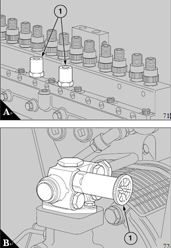
1 Loosen the low pressure relief valves (A1) on the
fuel injection pump and operate the priming plunger
(B1) of the fuel lift pump. When fuel, free from air,
flows from the relief valves, tighten the unions.
2 Clean away any fuel that has been spilled.
High-pressure system
Air in the high-pressure system must be releas ed at
the injectors.
1 Mov e the s top control to the RUN position and
operate the starter motor.
2 Loosen the nut of the high-pressure fuel pipe at one
of the injectors. When fuel, free from air, is released,
A
B
71
72
tighten the nut to a torque of 45 Nm (33 lbf ft). DO
NOT OVERTIGHTEN.
Warning! Ensure that fuel does not spray onto your
skin.
3 Repeat the procedure for the remainder of the fuel
injectors.
4 If the engine starts during this operation but runs
erratically, continue to eliminate air from each fuel
injector until the high-pressure sy stem is free from air
or until the engine runs correctly.
5 Return the stop control to the STOP position.
6 Clean away any fuel that has been spilled
400-100-8969???15088860848
0574-26871589? 15267810868
0574-26886646? 15706865167
0574-26871569 18658287286